Do you have a question about the Marantz PM350 and is the answer not in the manual?
Information on ordering Marantz parts domestically and internationally, including contact details.
Contact information for Marantz parts depots in Canada, Australia, Japan, and Europe for international service.
Manual purpose, service information for the Marantz PM350 Stereo Console Amplifier.
Details the signal flow and function of the pre-amplifier stage, including RIAA equalization.
Explains the main amplifier's high-pass filter network and its switching capability.
Addresses common problems like excessive power consumption, zero bias voltage, and hum or noise.
Step-by-step guide for adjusting the idling current on the power amplifier stages.
Procedure to calibrate the Power LED Meter to correctly indicate the 30W output level.
Lists essential test equipment and specific models needed for servicing the Marantz PM350.
Outlines preliminary steps and test setup configurations for verifying amplifier performance.
Procedures for measuring hum/noise levels, maximum power output, and distortion.
Detailed steps for measuring total harmonic distortion at various frequencies and output power levels.
Instructions for converting the unit to different power source voltages, primarily for European models.
Schematic representation of the PM350's internal signal flow and key component interconnections.
Detailed schematic diagram and component layout for the Main Amplifier Assembly (P700).
Schematic diagram and component placement for the Power Transistor Assembly (P701).
Schematic and component layout for the AC Switch Assembly (P000).
Schematic diagram and component placement for the Speaker Switch Assembly (PT00).
Schematic and component layout for the Head Phone Assembly (PW00).
Schematic diagram and component placement for the Tone Control Assembly (PE00).
Schematic and component layout for the LED Level Meter Drive Assembly (PX01).
Schematic diagram and component placement for the LED Level Meter Assembly (PX02).
Exploded view and list of part numbers for the front panel components and assembly.
Exploded view and list of part numbers for the top and bottom lid components.
Exploded view and list of part numbers for the rear panel components and assemblies.
Exploded view and list of part numbers for front chassis and general internal components.
Detailed identification of various internal components, transformers, switches, and jacks.
List of packing materials, instructions, and guarantee cards included with the unit.
List of resistors, capacitors, transistors, and switches for P700 and P701 boards.
List of components for P000, PT00, and PW00 boards, including resistors and switches.
List of resistors, capacitors, semiconductors, and jacks for PE01, PE03, PX01, PX02 boards.
List of components for PE02, PX01, PX02, and miscellaneous parts like jacks and LEDs.
Detailed audio performance parameters including power output, distortion, and frequency response.
Overall unit specifications covering power requirements, consumption, dimensions, and weight.
The complete schematic diagram showing all internal connections and component layouts of the PM350.
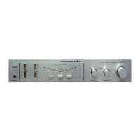
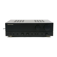
The Marantz PM350 is a stereophonic amplifier designed to deliver high-quality audio performance. This service manual provides comprehensive information for authorized warranty stations and experienced personnel to maintain and repair the device. It covers various aspects of the amplifier's operation, adjustment, troubleshooting, and component details.
The PM350 functions as a central hub for an audio system, amplifying signals from various sources and delivering them to speakers. It incorporates a pre-amplifier section, a main amplifier section, and several control circuits to manage audio signals and power.
The pre-amplifier section handles input signals from sources such as a tuner, auxiliary devices, and a phono input. Signals from the TUNER and AUX terminals are routed directly to the SELECTOR SWITCH. For PHONO inputs, signals first pass through a dedicated phono amplifier (Q401), which amplifies them by 35.5dB and applies RIAA equalization before reaching the SELECTOR SWITCH (SS02). This ensures that vinyl records are played back with accurate frequency response.
After selection, signals are directed to the TAPE MONITOR SWITCH and TAPE OUT terminals, allowing for recording or monitoring. Signals entering from the TAPE IN terminals are also routed to the TAPE MONITOR SWITCH. The selected signals then proceed to the BALANCE and VOLUME potentiometers for level and channel balance adjustments. Following these controls, the signals enter the main pre-amplifier (QE01), which provides an additional 18 dB of gain. The pre-amplified signals then pass through the TONE AMP (QE02), where the frequency response can be tailored using the BASS, MID, and TREBLE controls. Finally, the processed signals are fed into the main amplifier.
The main amplifier section is responsible for boosting the audio signals to a level suitable for driving speakers. It includes a 6 dB/OCT type high-pass filter network, which can be engaged or disengaged via the LOW FILTER switch, offering flexibility in sound shaping. The amplifier also features a power LED meter drive assembly (PX01) and a power LED meter assembly (PX02) to visually indicate output levels.
Power management is handled by the power transformer assembly (P701) and an AC switch assembly (P000). The device also includes a head phone assembly (PW00) for private listening.
The Marantz PM350 is designed for ease of use within a stereo audio setup. Users can connect various audio sources, including a turntable (PHONO), a tuner, and auxiliary devices, to the amplifier's input terminals. The SELECTOR SWITCH allows users to choose their desired input source.
For recording or monitoring, the TAPE MONITOR SWITCH and TAPE IN/OUT terminals provide convenient connectivity for tape decks or other recording equipment.
Audio output is provided through speaker terminals, allowing connection to a pair of stereo speakers. Additionally, a headphone jack is available for personal listening, enabling users to enjoy their audio without disturbing others.
The amplifier offers comprehensive tone control with BASS, MID, and TREBLE adjustments, allowing users to fine-tune the sound to their preferences or to compensate for room acoustics. A VOLUME control adjusts the overall output level, while a BALANCE control allows for precise adjustment of the left and right channel levels.
The LOW FILTER switch provides an option to engage a high-pass filter, which can be useful for removing unwanted low-frequency noise or rumble, particularly when playing vinyl records.
The power LED meter visually displays the output power, offering a dynamic indication of the amplifier's operation.
This service manual is a critical resource for maintaining the Marantz PM350. It outlines several key maintenance and adjustment procedures to ensure the amplifier operates to its original specifications.
Troubleshooting Analysis: The manual provides a troubleshooting guide for common issues such as excessive line consumption, no line consumption or zero bias voltage, and high hum and noise levels. This section directs technicians to specific components to check, such as transistors (Q801, Q729-Q732, Q709, Q710, Q807, Q808), resistors (R725, R726), rectifiers (Q801), inductors (L001), and filter capacitors (C801, C802, C807, C808).
Power Amplifier Adjustment: The manual details the procedure for adjusting the idling current of the power amplifier. This involves connecting a DC voltmeter between the emitters of specific transistors (Q729 and Q731, or Q730 and Q732) and adjusting corresponding resistors (R725, R726) until a specified voltage (11mV) is reached. This adjustment is crucial for optimal performance and longevity of the power output stage.
Power LED Meter Adjustment: Instructions are provided for calibrating the power LED meter. This involves connecting the speaker terminal output to a rated output voltage (15.5 V, 1 kHz) and adjusting specific resistors (RX07 for LCH, RX08 for RCH) until the 30W LED lights up, ensuring accurate visual representation of output power.
Performance Verification: A detailed section on performance verification outlines the test equipment required and preliminary procedures for conducting various tests, including:
Voltage Conversion: For European models, the manual includes instructions for converting the unit to operate on different power source voltages (e.g., 240V, 220V, 110V). This involves changing the position of a voltage selector switch, with a caution to disconnect the power supply cord before performing the conversion.
Exploded View and Parts List: The manual provides exploded views of various assemblies (Front Panel, Lid, Rear Panel, Front Chassis, and General Parts) along with detailed parts lists. These lists include part numbers, descriptions, and quantities, which are essential for ordering replacement components. A safety note emphasizes the importance of using designated parts for safety-critical components.
Schematic Diagrams and Component Locations: Detailed schematic diagrams and component location illustrations are provided for all major circuit boards, including the Main Amp Assembly (P700), Power Tr. Assembly (P701), AC Switch Assembly (P000), SP. Switch Assembly (PT00), Head Phone Assembly (PW00), Tone Control Assembly (PE00), LED Level Meter Drive Assembly (PX01), and LED Level Meter Assembly (PX02). These diagrams are invaluable for understanding circuit operation, diagnosing faults, and locating specific components during repair.
The manual also includes a comprehensive electrical parts list and technical specifications, providing all necessary information for thorough servicing and repair of the Marantz PM350 Stereophonic Amplifier.
| Type | Integrated Amplifier |
|---|---|
| Frequency Response | 10Hz-50kHz |
| Input Sensitivity | 2.5mV (MM), 150mV (line) |
| Output | Pre out |
| Total Harmonic Distortion | 0.05% |
| Speaker Load Impedance | 4Ω - 16Ω |