Do you have a question about the Marantz PM250 and is the answer not in the manual?
Service manual information for Marantz PM250/PM400, intended for experienced personnel.
Checks for shorted transistors and open components related to excessive power draw.
Checks for line cord, fuse, and shorted/open components causing no power or zero bias.
Troubleshooting steps for high hum and noise levels, focusing on filter capacitors.
Procedure to adjust idling current in the power amplifier using a DC voltmeter.
Procedure to calibrate the power meter using rated output voltage and specific resistors.
Details test equipment needed for servicing, including oscilloscopes, voltmeters, and signal generators.
Instructions for setting up test equipment and initial procedures for performance verification.
Procedure to measure total hum and noise levels with specific test conditions and volume settings.
Procedure to test maximum power output using an audio oscillator and AC VTVM.
Procedure to measure harmonic distortion at various frequencies using a distortion analyzer.
Instructions for changing the unit's voltage selector for different power sources.
Schematic diagram and component locations for the PX00 LED Power Meter Assembly.
Schematic diagram and component locations for the P700 Main Assembly.
Schematic diagram and component locations for the PY00 LED Lamp Assembly.
Schematic diagram and component locations for the PCOO Loudness Assembly.
Schematic diagram and component locations for the PJ00 Microphone Amplifier Assembly.
Schematic diagram and component locations for the PFOO Tone Assembly.
Schematic diagram and component locations for the PGOO Volume Assembly.
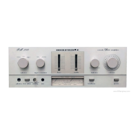
Exploded view and parts list for the PM400 front panel.
Exploded view and parts list for the PM250 front panel.
Exploded view and parts list for the top cover assembly.
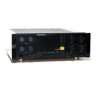
Exploded view and parts list for the rear panel assembly.
Exploded view and parts list for chassis and general components.
Exploded view and parts list for the PM250 Main P.W. Board.
Exploded view and parts list for the PM400 Main P.W. Board.
List of packing materials included with the unit.
Capacitors and resistors for the P700 Main Circuit Board.
Capacitors and resistors for Tone Amplifier and Volume Control circuits.
Lists various resistors and semiconductors for PX00, PG00, and PJ00 circuits.
Transistors, diodes, and other miscellaneous components for the P700 board.
Components for PF01 Tone Amp and PG00 Volume Control circuit boards.
Components for PJ00 Mic Amp, PS00 Loudness, PX00 LED, PY00 Pilot Lamp circuits.
Details power output, distortion, frequency response, and impedance for the PM250 audio section.
Includes power requirements, dimensions, weight, and semiconductor complement for PM250.
Power output, distortion, frequency response for the PM400 audio section.
Power requirements, dimensions, weight for the PM400 model.
| Total Harmonic Distortion (THD) | 0.1% |
|---|---|
| Input Sensitivity | 2.5mV (MM), 150mV (line) |
| Power Output | 25W per channel into 8Ω (stereo) |
| Speaker Load Impedance | 8Ω to 16Ω |
| Input Impedance | 47kΩ (MM) |