31
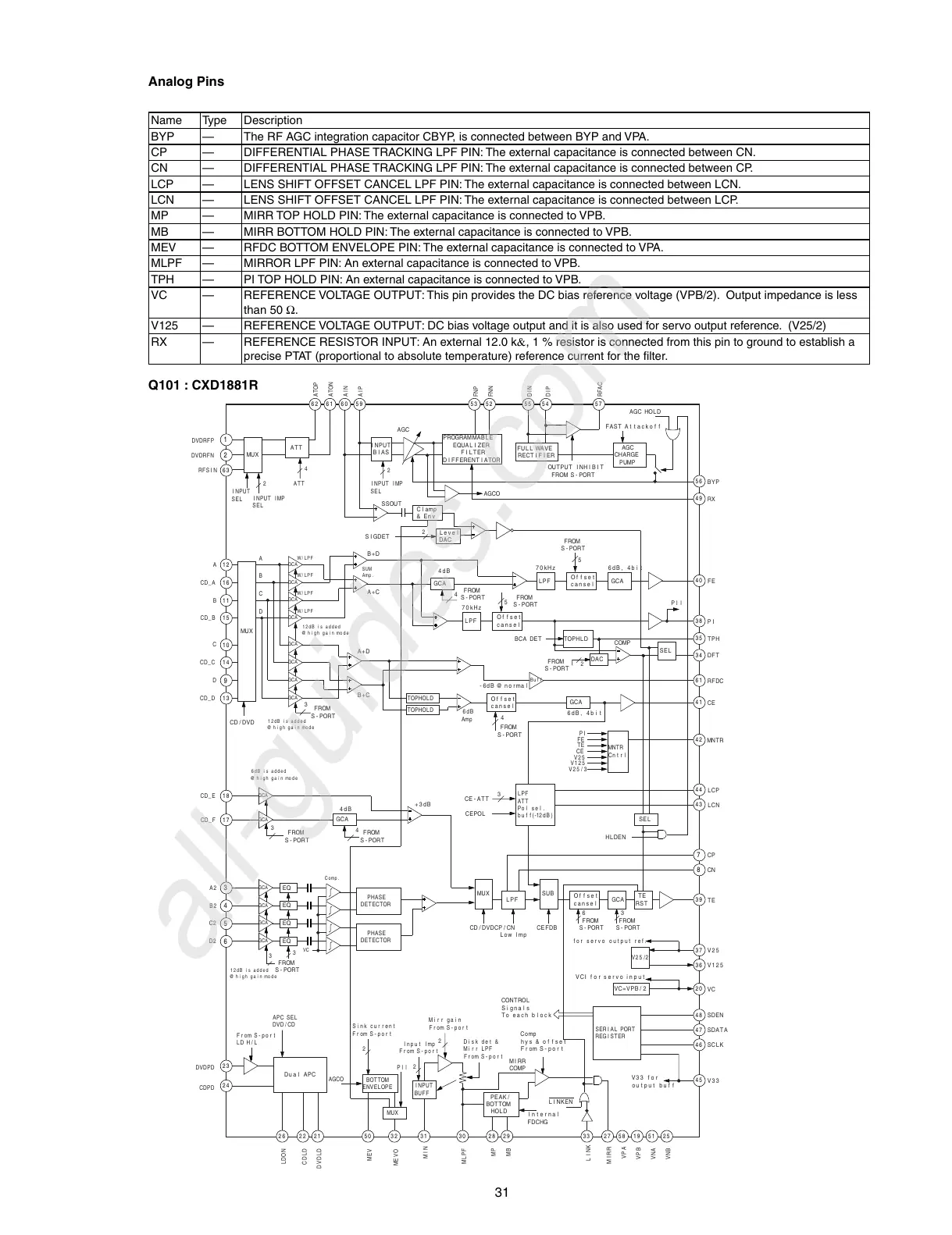
Analog Pins
Name Type Description
BYP — The RF AGC integration capacitor CBYP, is connected between BYP and VPA.
CP — DIFFERENTIAL PHASE TRACKING LPF PIN: The external capacitance is connected between CN.
CN — DIFFERENTIAL PHASE TRACKING LPF PIN: The external capacitance is connected between CP.
LCP — LENS SHIFT OFFSET CANCEL LPF PIN: The external capacitance is connected between LCN.
LCN — LENS SHIFT OFFSET CANCEL LPF PIN: The external capacitance is connected between LCP.
MP — MIRR TOP HOLD PIN: The external capacitance is connected to VPB.
MB — MIRR BOTTOM HOLD PIN: The external capacitance is connected to VPB.
MEV — RFDC BOTTOM ENVELOPE PIN: The external capacitance is connected to VPA.
MLPF — MIRROR LPF PIN: An external capacitance is connected to VPB.
TPH — PI TOP HOLD PIN: An external capacitance is connected to VPB.
VC — REFERENCE VOLTAGE OUTPUT: This pin provides the DC bias reference voltage (VPB/2). Output impedance is less
than 50 Ω.
V125 — REFERENCE VOLTAGE OUTPUT: DC bias voltage output and it is also used for servo output reference. (V25/2)
RX — REFERENCE RESISTOR INPUT: An external 12.0 k&, 1 % resistor is connected from this pin to ground to establish a
precise PTAT (proportional to absolute temperature) reference current for the fi lter.
DVDRFP
DVDRFN
RFSI N
ATOP
ATON
AIN
AIP
FNP
DIN
DIP
RFAC
FNN
MUX
INPUT
BIAS
ATT
63
A
12
CD_A
16
B 11
CD_B 15
C
10
CD_C 14
D
CD_D 13
CD_E
18
CD_F 17
2
9
A2
3
1
INPUT
SEL
INPUT IMP
SEL
2
INPUT IMP
SEL
2
2
4
ATT
62 61 60 59
AGC
PROGRAMMABLE
EQUAL I ZER
FILTER
DIFFERENTIATOR
AGCO
53 52
SSOUT
Clamp
& Env
Leve l
DAC
SIGDET
FULL WAVE
RECT I FI ER
OUTPUT INHIBIT
FROM S-PORT
55 54 57
56
AGC
CHARGE
PUMP
FAST A t tacko f f
AGC HOLD
B+D
A+C
A+D
B+C
MUX
D
C
B
A
GCA
GCA
GCA
GCA
GCA
GCA
GCA
GCA
W/LPF
W/LPF
W/LPF
W/LPF
SUM
Amp .
12dB i s added
@ h igh gain mode
12dB i s added
@ high gain mode
6dB is added
@ high gain mode
12dB i s added
@ h i gh g a i n mod e
3
3
4
FROM
S-PORT
FROM
S-PORT
FROM
S-PORT
FROM
S-PORT
CD /DVD
GCA
4dB
Of fset
cansel
LPF GCA
70kHz 6dB, 4bi t
6dB, 4bi t
4dB
4
4
FROM
S-PORT
FROM
S-PORT
5
Of fset
cansel
LPF
70kHz
FROM
S-PORT
FROM
S-PORT
FROM
S-PORT
FROM
S-PORT
5
TOPHLD
BCA DET
- 6dB @ no rma l
COMP
Pl l
SEL
BYP
49
RX
40
FE
38
PI
35
TPH
34
DFT
RFDC
DAC
2
Buf f
61
CE
41
MNTR
TOPHOLD
TOPHOLD
6dB
Amp
Of fset
cansel
GCA
GCA SEL
MNTR
Cn t r l
PI
FE
TE
CE
V25
V125
V25 /3
42
LCP
44
LCN
43
TE
CP
LPF
ATT
Po l se l .
buf f(-12dB)
HLDEN
3
3
CE -ATT
CEPOL
+3dB
GCA
GCA
GCA
7
CN
8
Of fset
cansel
LPF GCA
SUBMU X
TE
RST
39
V25
37
V125
36
VC
20
SDEN
48
SDATA
47
SCLK
46
V33
45
FROM
S-PORT
6
CEFDBCD/ DVDCP/ CN
Low lmp
EQ
B2
4
C2
5
D2
CDPD
6
GCA
GCA
GCA
PHASE
DETECTOR
PHASE
DETECTOR
EQ
EQ
EQ
3
3
VC
Comp .
V25 /2
for servo output ref.
VC=VPB / 2
VCI for servo input
SERI AL PORT
REGI STER
V33 f or
output buf f
MIRR
27
LINK
VPA
58
VPB
19
VNA
51
VNB
2533
MB
29
MP
28
MLPF
30
MIN
31
MEVO
32
MEV
LINKEN
MIRR
COMP
Comp
hys & offset
From S-port
CONTROL
Signals
To each block
PEAK /
BOTTOM
HOLD
Internal
FDCHG
Disk det &
Mi rr LPF
From S-port
2
2
2
Mi rr gain
From S-por t
INPUT
BUFF
Input lmp
From S-port
MUX
Pll
50
DVDLD
21
CDLD
22
LDON
26
BOTTOM
ENVELOPE
AGCO
Sink current
From S-port
Dual APC
24
DVDPD
23
APC SEL
DVD/ CD
From S-port
LD H/ L
Q101 : CXD1881R

 Loading...