32
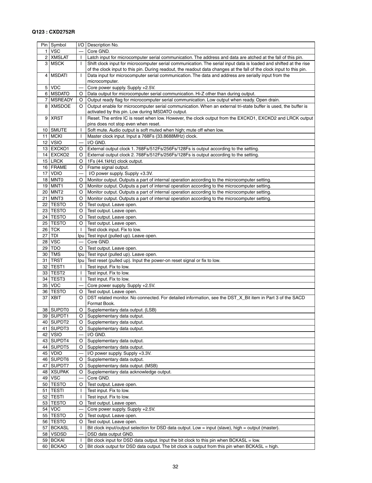
Pin Symbol I/O Description No.
1 VSC — Core GND.
2 XMSLAT I Latch input for microcomputer serial communication. The address and data are atched at the fall of this pin.
3 MSCK I Shift clock input for microcomputer serial communication. The serial input data is loaded and shifted at the rise
of the clock input to this pin. During readout, the readout data changes at the fall of the clock input to this pin.
4 MSDATI I Data input for microcomputer serial communication. The data and address are serially input from the
microcomputer.
5 VDC — Core power supply. Supply +2.5V.
6 MSDATO O Data output for microcomputer serial communication. Hi-Z other than during output.
7 MSREADY O Output ready fl ag for microcomputer serial communication. Low output when ready. Open drain.
8 XMSDOE O Output enable for microcomputer serial communication. When an external tri-state buffer is used, the buffer is
activated by this pin. Low during MSDATO output.
9 XRST I Reset. The entire IC is reset when low. However, the clock output from the EXCKO1, EXCKO2 and LRCK output
pins does not stop even when reset.
10 SMUTE I Soft mute. Audio output is soft muted when high; mute off when low.
11 MCKI I Master clock input. Input a 768Fs (33.8688MHz) clock.
12 VSIO — I/O GND.
13 EXCKO1 O External output clock 1. 768Fs/512Fs/256Fs/128Fs is output according to the setting.
14 EXCKO2 O External output clock 2. 768Fs/512Fs/256Fs/128Fs is output according to the setting.
15 LRCK O 1Fs (44.1kHz) clock output.
16 FRAME O Frame signal output.
17 VDIO — I/O power supply. Supply +3.3V.
18 MNT0 O Monitor output. Outputs a part of internal operation according to the microcomputer setting.
19 MNT1 O Monitor output. Outputs a part of internal operation according to the microcomputer setting.
20 MNT2 O Monitor output. Outputs a part of internal operation according to the microcomputer setting.
21 MNT3 O Monitor output. Outputs a part of internal operation according to the microcomputer setting.
22 TESTO O Test output. Leave open.
23 TESTO O Test output. Leave open.
24 TESTO O Test output. Leave open.
25 TESTO O Test output. Leave open.
26 TCK I Test clock input. Fix to low.
27 TDI Ipu Test input (pulled up). Leave open.
28 VSC — Core GND.
29 TDO O Test output. Leave open.
30 TMS Ipu Test input (pulled up). Leave open.
31 TRST Ipu Test reset (pulled up). Input the power-on reset signal or fi x to low.
32 TEST1 I Test input. Fix to low.
33 TEST2 I Test input. Fix to low.
34 TEST3 I Test input. Fix to low.
35 VDC — Core power supply. Supply +2.5V.
36 TESTO O Test output. Leave open.
37 XBIT O DST related monitor. No connected. For detailed information, see the DST_X_Bit item in Part 3 of the SACD
Format Book.
38 SUPDT0 O Supplementary data output. (LSB)
39 SUPDT1 O Supplementary data output.
40 SUPDT2 O Supplementary data output.
41 SUPDT3 O Supplementary data output.
42 VSIO — I/O GND.
43 SUPDT4 O Supplementary data output.
44 SUPDT5 O Supplementary data output.
45 VDIO — I/O power supply. Supply +3.3V.
46 SUPDT6 O Supplementary data output.
47 SUPDT7 O Supplementary data output. (MSB)
48 XSUPAK O Supplementary data acknowledge output.
49 VSC — Core GND.
50 TESTO O Test output. Leave open.
51 TESTI I Test input. Fix to low.
52 TESTI I Test input. Fix to low.
53 TESTO O Test output. Leave open.
54 VDC — Core power supply. Supply +2.5V.
55 TESTO O Test output. Leave open.
56 TESTO O Test output. Leave open.
57 BCKASL I Bit clock input/output selection for DSD data output. Low = input (slave), high = output (master).
58 VSDSD — DSD data output GND.
59 BCKAI I Bit clock input for DSD data output. Input the bit clock to this pin when BCKASL = low.
60 BCKAO O Bit clock output for DSD data output. The bit clock is output from this pin when BCKASL = high.
Q123 : CXD2752R

 Loading...