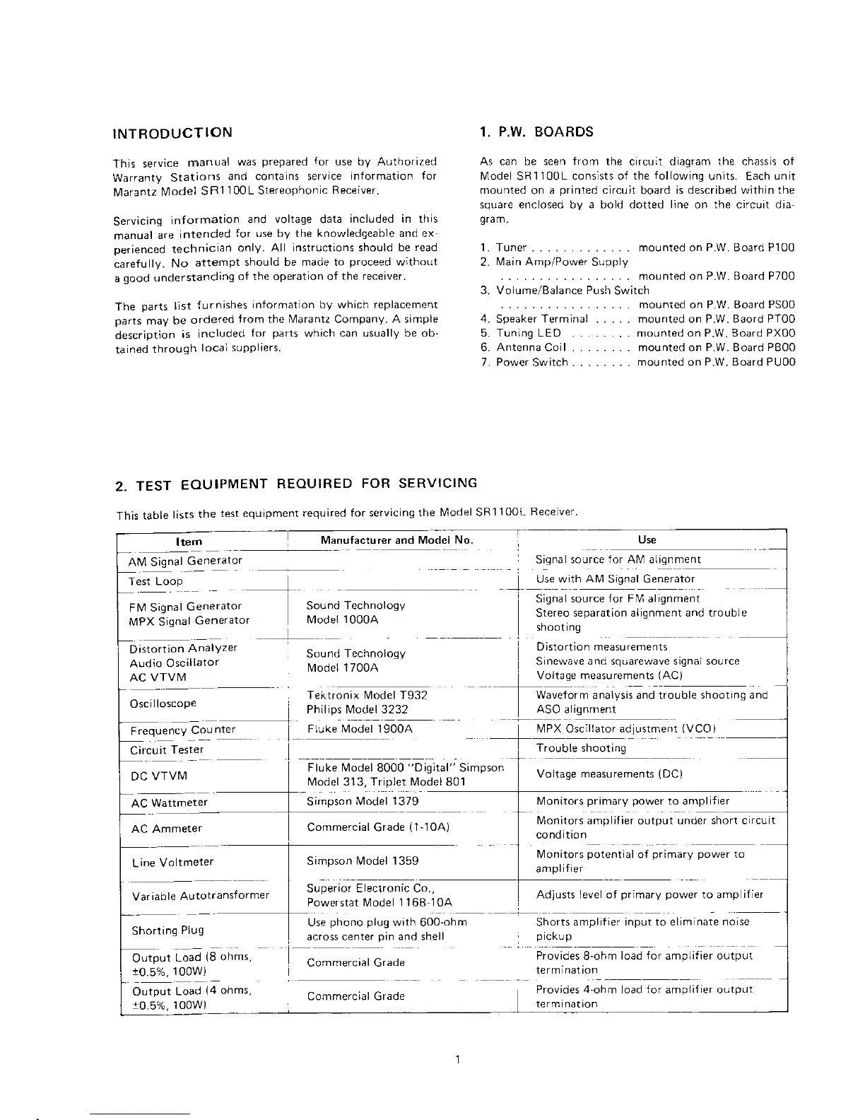
INTRODUCTION
This
service
manual
was
prepared
for
use by Authorized
Warranty Stations
and contains service
information for
lMarantz
lvlodel
SF1
100L
Stereophonic
Receiver.
Servicing
information
and
voltage
data
included in this
manual
are
intended
for use by the knowledgeable and ex
perienced
technician
only-
All instructions should be
read
carefully.
No
atternpt
should be made to
proceed
without
a
good understanding
of the operation of
the receiver.
The
parts
list
{urnishes
information by which replacement
parts
may
be
ordered
Jrom the N4aranlz Company. A simple
description
is
included
for
parts
which
can usually be ob'
tained
through
local
suPPliers
2.
TEST
EOUIPMENT
REOUIRED
FOR SERVICING
Item
Manufacturer and Model
No.
Alvl Signal
Generator
't.
P.w. BoABDS
As can be seen from the
circuit
diagram the chassis of
l4odel SR1100L
cons]sts of the
following
units. Each
unit
mounted
on
a
printed
circuit
board
is described within the
square enclosed by a bold dotted line on the circuit dia-
gram.
1. Tuner . . - mounted on P-W. Board P100
2.
Main
Amp/Power Supply
. mounted on
P.W. Board P700
3. Volume/Balance Push
Switch
mounted on P.W. Board PS00
4.
Speaker
Terminal
. . . . mounted on P.W. Baord
PT00
5. Tuning LED . . . .. .. mounted on P.W. Board PX00
6. Antenna Coil mounted on P.W. Board PB00
7. Power
Switch
mounted on P.W. Board PU00
Use
Signal
source for AM alignment
Test Loop
Use wlth
AM
Signal Generator
FIM Signal
Generator
Sound
Technology
Signal source
for FM
alignment
MPX Oscillator adjLrstment
(VCO
)
Trouble shooting
Voltage measurements
(DC)
lvlonitors
primary power
to amplif
ier
Stereo
separation alignment and troLrble
shootrng
Distortion measurements
Sinewave
and squarewave signaJ sourc-"
Voltage measurements
lAC)
Waveform
analysis and trouble
shooting and
ASO
alignment
Oscilloscope
FrequencY
Cou
nter
Fluke Model 19004
Flukp l\,4odel
8000
"Dig.tal"
Simpson
f\4odel 313, Triplet Model 801
Simpson Model
1379
Commercial Grade
(1-10A)
Simpson
Model 1359
Tektronix Model T932
Philips l,.4odel 3232
Superior Electronic Co.,
Circuit
Tester
DC
VTVM
AC
Wattmeter
Output
Load
r0.5%, 100w)
AC Ammeter
Line
Voltmeter
Variable
Autotransformer
Shorting
Plug
Powerstat
l\4odel 1 168-10A
lMonitors amplifier
output
under short crrcu t
cond ition
Monitors
potential
of
primary power
to
am
p
lifier
Use
phono plug
with 600-ohm
across center
pin
and shell
Commercial Grade
Shorts
amplifier input to eliminate
norse
p
rcKLr
p
Adjusts'evel ot
pr
mary
power
to dmp
if er
Provides 8-ohm
load Jor
amplifier
output
termrnar ron
This
table
lists
the
test equipment
required for servicing
the N4odel SR
1
100L Receiver'
Commercial Grade
Output
Load
10.5%,
100w)
Provides 4 ohm oad for amplifier output
rermtna( ton