Do you have a question about the Marantz SR390 and is the answer not in the manual?
Instructions for ordering replacement parts for Marantz equipment.
Safety precautions for testing and servicing the appliance before returning to the customer.
Technical details for the FM tuner functionality.
Technical details for the AM tuner functionality.
Technical details for the audio output and performance.
Technical details for the video input/output specifications.
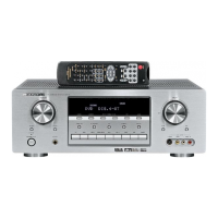
Physical dimensions and weight of the audio/video receiver.
Details on speaker selection switches and headphone output circuitry.
Schematic for the auxiliary input section.
PCB layout and details for the volume control circuit.
Procedure for adjusting the tracking voltage for FM and AM signals.
Procedure for adjusting the RF parameters for the AM tuner.
Procedure for adjusting the RF parameters for the FM tuner.
Procedure for adjusting the mono distortion in the FM tuner.
Procedure for adjusting the FM multiplex VCO for optimal performance.
Procedure for adjusting the stereo separation for FM signals.
Procedure for adjusting the auto stop levels for AM and FM tuning.
Common part codes and specifications for resistors used in the unit.
Common part codes and specifications for capacitors used in the unit.
Important safety warnings regarding component replacement and common abbreviations used.
| Total Harmonic Distortion | 0.08% |
|---|---|
| Power Output | 50 watts per channel into 8Ω (stereo) |
| Frequency Response | 20Hz-20kHz |
| Input Sensitivity | 200mV |
| Signal to Noise Ratio | 80dB |
| Speaker Load Impedance | 8Ω to 16Ω |
| Video Connections | composite |
| Tuning range | FM |
| Video Inputs | 1 composite |
| Video Outputs | 1 composite video output |
| Audio Outputs | tape, video |