EasyManua.ls Logo

Marantz SR-14 User Manual

Marantz SR-14
60 pages
To Next Page IconTo Next Page
Page #1 background imageLoading...
Page #1 background image
AV Surround Receiver
SR-14
322J855010 MIT
3120 785 22240
First Issue 1999.11
Service
Manual
SR14 /K1G, /N1G, /S1G
R
SR-14
Please use this service manual with referring to the user guide ( D.F.U. ) without fail.
TABLE OF CONTENTS
SECTION PAGE
1. TECHNICAL SPECIFICATIONS ................................................................................................................. 1
2. WIRING DIAGRAM ..................................................................................................................................... 3
3. BLOCK DIAGRAM ....................................................................................................................................... 5
4. SCHEMATIC DIAGRAM .............................................................................................................................. 7
5. PARTS LOCATION (Pattern Side) ............................................................................................................ 25
6. IC DATA .................................................................................................................................................... 45
7. EXPLODED VIEW AND PARTS LIST ....................................................................................................... 53
8. SERVICE PROGRAM ............................................................................................................................... 57
9. ELECTRICAL ADJUSTMENTS ................................................................................................................. 59
10. ALIGNMENT PROCEDURES ................................................................................................................... 61
11. TROUBLE SHOOTING ............................................................................................................................. 63
12. TECHNICAL DESCRIPTION FOR DECODER ......................................................................................... 66
13. ELECTRICAL PARTS LIST ....................................................................................................................... 68
POWER ON / OFF
PHONES
A/D ATT
AUTO DOLBY
BAND FM MODE
THX DTS
MEMO
HALL
CL
MATRIX
D.COPY
MOVIE
TAPE
COPY
VCR1
ST/MONO S.DIRECT
TONE CONTROL
BASS TREBLE
S2-VIDEO VIDEO L AUDIO R
AUX INPUT
INPUT SELECTOR
AV SURROUND RECEIVER SR-14
dts
CINEMA
MUSIC
96 kHz
TV
LD
DVD
DOWN
GYRO TUNING UP
VCR1 DSS/VCR2
AUX
PRESET AUTO TUNINGDISPLAY OFF MULTI
DOWN UP
VOLUME
LC R
LFE
LS S RS
PEAK
STANDBY
Question and Answer IconNeed help?

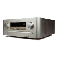
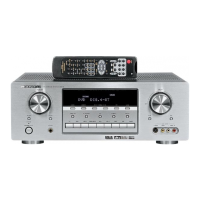
Do you have a question about the Marantz SR-14 and is the answer not in the manual?

Marantz SR-14 Specifications

General IconGeneral
TypeAV Receiver
Total Harmonic Distortion0.05%
Wireless ConnectivityNo
Tuner SectionAM/FM
Digital InputsCoaxial, Optical
Input Sensitivity200mV
Video ConnectionsComposite, S-Video
Audio Formats SupportedDolby Digital, DTS
Zone 2/Zone 3 OutputsZone 2
Video InputsComposite, S-Video
Video OutputsComposite, S-Video
Digital OutputsCoaxial

Summary

Marantz Design Philosophy

Ordering Service Parts

1. Technical Specifications

FM Tuner Section Specifications

Details performance parameters for the FM tuner.

AM/LW Tuner Section Specifications

Details performance parameters for AM/LW tuners.

Audio Section Specifications

Lists power ratings, input sensitivity, and noise levels for audio.

Video and General Specifications

Covers television formats, input/output levels, and power requirements.

3. Block Diagram

4. Schematic Diagram

5. Parts Location Diagrams (Part 1)

5. Parts Location Diagrams (Part 2)

8. Service Program

Factory Mode Operations

Details procedures for entering and using factory test modes for tuning.

Display Segment Check Mode

Describes how to test all segments of the display.

Microprocessor Version Check

Explains how to confirm CPU program versions.

Input/Output Test Mode

Outlines tests for verifying audio input and output signals.

Transistor Mute Mode Operation

Details how to activate the muting transistor circuit.

Product Reset Procedure

Instructions on how to reset the unit to default settings.

9. Electrical Adjustments

DC Offset Adjustment Procedure

Steps to adjust DC offset voltage at speaker terminals.

Idling Current Adjustment Procedure

Procedures and tables for adjusting idling current.

Thermostat Circuit Confirmation

Steps to confirm the thermostat circuit functionality.

4. Cooling Fan Confirmation

Fan Failure Sensor Test

Procedure to check the fan failure detection mechanism.

Temperature Sensor Test

How to test the cooling fan's response to temperature sensors.

Foreign Body Sensor Test

Verifies fan operation when airflow is obstructed.

10. Alignment Procedures

AM IF Adjustment

Steps for aligning the AM Intermediate Frequency circuit.

AM (MW) Tracking Adjustment

Procedure for optimizing MW tracking for sensitivity.

AM (LW) Tracking Adjustment

Procedure for optimizing LW tracking for sensitivity.

AM Auto Stop Adjustment

Steps to adjust the AM tuning auto-stop function.

FM Mono Distortion Adjustment

How to minimize distortion in FM mono reception.

6. FM Muting Level Adjustment

7. FM Stereo Distortion Adjustment

8. FM Stereo Separation Adjustment

11. Troubleshooting Guide

12. Technical Description

Dolby Digital (AC-3) System

Explains the 6-channel discrete audio format and its features.

DTS Digital Surround Technology

Describes the DTS encode/decode system for surround sound.

THX Ultra Processing

Details Home THX controller technologies for cinema sound.

Digital Audio Interface Receiver (DIR)

Circuit description for extracting clock and data from SPDIF input.

1st DSP Functionality

Role of the first DSP in multi-channel decoding and effects.

2nd DSP and Audio Converters

THX Processing DSP Functions

Explains Re-equalization, Timbre Matching, Decorrelation, Bass Management.

Analog-to-Digital Converter (ADC)

Details the CS5394 ADC for stereo digital audio.

Digital-to-Analog Converter (DAC)

Describes the AD1855 DAC chips for audio output.

CPU Control Functions

Role of the CPU in controlling ICs and communication.

13. Electrical Parts List