EasyManua.ls Logo

Marantz sr-18 u User Manual

Marantz sr-18 u
60 pages
To Next Page IconTo Next Page
Page #1 background imageLoading...
Page #1 background image
Printed in Japan
AV Surround Receiver
model SR-18
First Issue 1999.07
300J855010 MIT
TABLE OF CONTENTS
SECTION PAGE
1. TECHNICAL SPECIFICATIONS ................................................................................................................. 1
2. WIRING DIAGRAM ..................................................................................................................................... 3
3. BLOCK DIAGRAM....................................................................................................................................... 5
4. SCHEMATIC DIAGRAM.............................................................................................................................. 7
5. PARTS LOCATION (Pattern Side) ............................................................................................................ 25
6. IC DATA .................................................................................................................................................... 45
7. EXPLODED VIEW AND PARTS LIST....................................................................................................... 53
8. SERVICE PROGRAM ............................................................................................................................... 57
9. ELECTRICAL ADJUSTMENTS ................................................................................................................. 59
10. ALIGNMENT PROCEDURES ................................................................................................................... 61
11. TROUBLE SHOOTING ............................................................................................................................. 63
12. TECHNICAL DESCRIPTION FOR DECODER ......................................................................................... 66
13. ELECTRICAL PARTS LIST ....................................................................................................................... 68
Service
Manual
SR-18 U, K, KS
Please use this service manual with referring to the user guide (D.F.U) without fail.
R
POWER/STANDBY
PHONES
A/D ATT
AUTO DOLBY
BAND FM MODE
THX DTS
MEMO
HALL
CL
MATRIX
D.COPY
MOVIE
TAPE
COPY
VCR1
ST/MONO S.DIRECT
TONE CONTROL
BASS TREBLE
S2-VIDEO VIDEO L AUDIO R
AUX INPUT
INPUT SELECTOR
AV SURROUND RECEIVER SR-18
dts
CINEMA
MUSIC
96 kHz
TV
LD
DVD
DOWN
GYRO TUNING UP
VCR1 DSS/VCR2
AUX
PRESET AUTO TUNINGDISPLAY OFF MULTI
DOWN UP
VOLUME
LCR
LFE
LS S RS
PEAK
Question and Answer IconNeed help?

Do you have a question about the Marantz sr-18 u and is the answer not in the manual?

Marantz sr-18 u Specifications

General IconGeneral
TypeAV Receiver
Channels5.1
Power output140W per channel (8 ohms, 20Hz-20kHz, 0.05% THD)
Frequency response10Hz-100kHz (+1, -3dB)
Total Harmonic Distortion0.05%
Signal to noise ratio100dB
Video ConnectionsComposite, S-Video
Dimensions175 x 440 x 470 mm
Weight21.5 kg
Tuner TypeAM/FM
Surround SoundDolby Digital, DTS
Input sensitivity200mV
Outputs2 audio outputs, 3 video outputs

Summary

Technical Specifications

FM TUNER SECTION

Specifications for the FM tuner receiver section.

AM TUNER SECTION

Specifications for the AM tuner receiver section.

AUDIO SECTION

Specifications for audio output power, input sensitivity, and S/N.

VIDEO

Specifications for video input/output levels and frequency response.

GENERAL

General unit specifications including power and dimensions.

Diagrams and Schematics

Wiring Diagram

Diagram showing electrical interconnections between components.

Block Diagram

Functional overview of the unit's main circuit blocks.

Schematic Diagram

Detailed circuit schematics for all sections of the receiver.

Component Information

Parts Location (Pattern Side)

Physical placement of components on circuit boards (pattern side).

IC Data

Technical details and pinouts for integrated circuits used.

Exploded View and Parts List

Visual breakdown of the unit with a corresponding parts list.

Electrical Parts List

Comprehensive list of all electrical components used in the unit.

Service and Maintenance

Service Program

Special modes for testing, calibration, and setup.

Electrical Adjustments

Procedures for adjusting DC offset, idling current, and thermostat circuits.

Alignment Procedures

Steps for aligning tuner sections and other circuits for optimal performance.

Troubleshooting and Technical Description

Troubleshooting

Diagnostic flowcharts for diagnosing and resolving common issues.

Technical Description

Explanations of the unit's audio processing technologies like Dolby Digital and DTS.
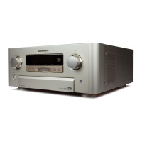
Related product manuals