59
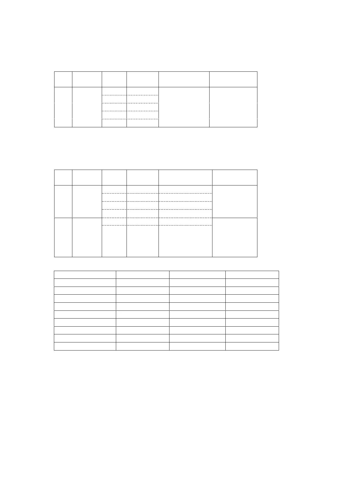
1. DC offset adjustment
Master Volume : Minimum, Speaker out : non Load
Step Power Channel
Adjustment
Point
Test Point Adjustment Vaule
Front L R715
Center RT15
Front R RP16
Surr. L RP15
1on
Surr. R R716
Speaker Output
Terminal
20mV
±
Note : If the measured value is not exceed ±20mV, no need to adjust the DC offset.
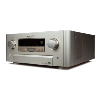
2. Iding current adjustment
Master Volume : Minimum, Speaker out : non Load
Step Power Channel
Adjustment
Point
Test Point
Adjustment
Vaule
Front L R743 J713 or R773
Center RT43 JT13 or RT73
Front R RP44 JP04 or RP74
1 Power on
Surr. L RP43 JP03 or RP73
within 1 minute
0.4mV
Surr. R R744 J714 or R774
2
after
4 minutes
J***:4P Connecter
(between 1p-4p)
R***:Emitter Resister
(0.1ohms x2)
see table
for adjustment
vaule
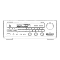
Time since power on Idling current adjust. Time since power on Idling current adjust.
4–4 minutes 30 seconds 5.6mV 11-12 minutes 8.0mV
4m30s–5 minutes 6.4mV 12-14 minutes 7.6mV
5–5 minutes 30 seconds 7.2mV 14-16 minutes 7.2mV
5m30s–6 minutes 7.7mV 16-18 minutes 6.5mV
6–7 minutes 8.2mV 18-22 minutes 5.6mV
7-8 minutes 8.6mV 22-26 minutes 4.9mV
8-9 minutes 8.8mV 26-30 minutes 4.4mV
9-10 minutes 8.6mV more than 30 minutes 4.0mV
10-11 minutes 8.4mV The taget is 4.0mV
3. Thermostat circuit confirmation
1) When the product is POWER ON, remove the wire W701 from the connector J715 (P704).
2) FLD shows "ERROR PWR1".
3) Confirm the product is POWER OFF after 3 seconds.
4) Connect the wire W701 to the connector J715 (on P704).
5) Confirm the product is standby status.
9. ELECTRICAL ADJUSTMENTS