EasyManua.ls Logo

Marantz SR-66 - Service Manual

Marantz SR-66
28 pages
Print Icon
To Next Page IconTo Next Page
Loading...
Service
74
SR66/o28
SR-66U
Manual
A/V
Surround
Receiver
TABLE
OF
CONTENTS
SECTION
vg
PAGE
1:
TECHNICAL
SPECIFICATIONS
:scjieaisss
sai
asstuicesndssesisceanielaee
neat
atid
lett
cee
eee
chee
a
DBE
OC
K
DUA
GRAIN
seca
Sc
aaa
ea
ened
en
geld
cst
hee
ash
toa
Sectareeenseee
Zo
BS
WIRING
DIAGRANA
gece
teeter
at
seep
hia
Dae
Oat
Basic
Soeceal
a
sintaa
ete
oiehuucaocaaeate
.7
4.
SCHEMATIC
DIAGRAM
AND
PARTS
LOCATION
(Pattern
Side)
......sssscsssssssessseessetessserssneeessnenamuneetersses
.9
5.
SERVICE
TEST
PROGRAM
OF
THE
MICROPROCESSOR
........ssscsssssssseccessssssseseessssneescenuneseeesmenet
tenes
24
6.
ALIGNMENT
PROCEDURES
fcc
eiscctanaiii
Geeeceee
ain
ietg
imran
eae
aecaationeaaset
28
7:
EXPLODED
VIEWAND
PARTS
LIST
ste
ccisis
san
ie
etendgemnuconnieneeaaenimen
alent
32
BU
ELEGTARICAM
PARTS
LIST
cnuituarswacinadanueetisnvarhiumuns
iar
oan
Coen
eases
35
Please
use
this
service
manual
with
referring
to
the
user
guide
(D.F.U)
without
jail.
model
SR-66
Printed
in
Japan
First
§ssue
1996.3
4168w
855080
ACT
Question and Answer IconNeed help?

Do you have a question about the Marantz SR-66 and is the answer not in the manual?

Summary

Service Manual

1. TECHNICAL SPECIFICATIONS

Detailed technical specifications for audio and tuner sections.

2. BLOCK DIAGRAM

High-level functional overview of system components and connections.

3. WIRING DIAGRAM

Detailed electrical connections between boards and components.

4. SCHEMATIC DIAGRAM AND PARTS LOCATION (Pattern Side)

Circuit diagrams and component layout on PCBs.

5. SERVICE TEST PROGRAM OF THE MICROPROCESSOR

Procedures for microprocessor-based testing and diagnostics.

6. ALIGNMENT PROCEDURES

Step-by-step instructions for calibrating the unit's performance.

7. EXPLODED VIEW AND PARTS LIST

Visual breakdown with a list of all parts for assembly/disassembly.

8. ELECTRICAL PARTS LIST

Comprehensive list of all electronic components used.

MARANTZ DESIGN AND SERVICE

ORDERING PARTS

Instructions and required information for obtaining replacement Marantz parts.

SHOCK, FIRE HAZARD SERVICE TEST

Critical safety test procedures before returning unit to customer.

TECHNICAL SPECIFICATIONS

FRONT AMP SECTION

Performance specifications for the front amplifier stage.

CENTER AMP SECTION

Performance specifications for the center amplifier stage.

REAR AMP SECTION

Performance specifications for the rear amplifier stages.

TECHNICAL SPECIFICATIONS (continued)

FM SECTION

Performance specifications for the FM tuner section.

MPX SECTION

Specifications related to the multiplex (MPX) decoder.

AM SECTION

Performance specifications for the AM tuner section.

TECHNICAL SPECIFICATIONS (continued)

GENERAL SPECIFICATIONS

General physical and electrical characteristics of the unit.

POWER REQUIREMENTS

Details on power input voltage and frequency.

BLOCK DIAGRAM

WIRING DIAGRAM

SCHEMATIC DIAGRAM AND PARTS LOCATION (Pattern Side)

SCHEMATIC DIAGRAM AND PARTS LOCATION (Pattern Side) (continued)

SCHEMATIC DIAGRAM AND PARTS LOCATION (Pattern Side) (continued)

Printed Circuit Board Diagrams

VCR2 Board Diagram

Layout and component placement for the VCR2 PC board.

Tuner Board Diagram

Layout and component placement for the Tuner PC board.

Printed Circuit Board Diagrams (continued)

Front Board Diagram

Layout and component placement for the Front PC board.

Printed Circuit Board Diagrams (continued)

Front Board Diagram (continued)

Further details on the Front PC board layout.

Printed Circuit Board Diagrams (continued)

Power Supply Board Diagram

Layout and component placement for the Power Supply PC board.

Printed Circuit Board Diagrams (continued)

Power Supply Board Diagram (continued)

Further details on the Power Supply PC board layout.

SERVICE TEST PROGRAM OF THE MICROPROCESSOR

Microprocessor Pin Configuration

Detailed pin assignments and functions for the microprocessor IC.

Microprocessor Key Matrix

Mapping of input keys to scan codes and functions.

SERVICE TEST PROGRAM OF THE MICROPROCESSOR (continued)

Microprocessor Key Matrix (continued)

Table detailing key inputs and their corresponding output functions.

Microprocessor Block Diagram

Simplified diagram illustrating CPU interfaces and peripherals.

SERVICE TEST PROGRAM OF THE MICROPROCESSOR (continued)

Microprocessor Pin Functions

Detailed description of each pin's function for the microprocessor.

CH. MODE Settings

Settings for PRO-LOGIC and 3-STEREO modes.

STEP Settings for FM;AM Bands

Input for selecting FM/AM frequency bands and steps.

SERVICE TEST PROGRAM OF THE MICROPROCESSOR (continued)

Microprocessor Pin Functions (continued)

Further details on microprocessor pin functions.

Center Mode and VCR Signal Settings

Control data for center modes and VCR signal selection.

ALIGNMENT PROCEDURES

Equipment Required for Alignment

List of essential test equipment for performing alignments.

Alignment Test Points (Tuner Board)

Identifies key test points and adjustment components on the tuner board.

ALIGNMENT PROCEDURES (continued)

AM IF, RF, and Tuning Voltage Alignment

Step-by-step guide for aligning the AM tuner circuits.

FM IF Alignment

Step-by-step guide for aligning the FM tuner IF circuits.

ALIGNMENT PROCEDURES (continued)

AM and FM Alignment Connection Diagrams

Diagrams showing test setup connections for AM and FM alignment.

ALIGNMENT PROCEDURES (continued)

MPX Alignment Procedures

Procedures for aligning the multiplex (MPX) section of the tuner.

EXPLODED VIEW AND PARTS LIST

Cabinet and Chassis Parts

List of parts for the unit's external casing and structure.

Miscellaneous Parts

List of parts not fitting other specific categories.

Accessories Parts

List of included accessories like manuals and remote control.

ELECTRICAL PARTS LIST

Resistor Components

List of resistors with their specifications.

Capacitor Components

List of capacitors with their specifications.

Diode Components

List of diodes with their specifications.

Transistor Components

List of transistors with their specifications.

ELECTRICAL PARTS LIST (continued)

Tuner and Front PC Board Parts

Parts list specific to the Tuner and Front PC boards.

ELECTRICAL PARTS LIST (continued)

Speaker Selector, Headphone, and Power Supply Board Parts

Parts list for speaker selector, headphone, and power supply boards.

Overview

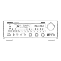
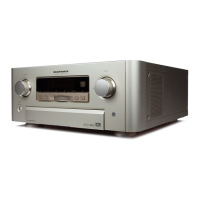
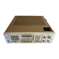
The Marantz SR-66 is an A/V Surround Receiver, designed to deliver a high-quality audio-visual experience. This service manual provides comprehensive information for the maintenance, repair, and alignment of the device, ensuring its continued optimal performance.

Function Description

The SR-66 functions as a central hub for various audio and video sources, processing and amplifying signals to drive a multi-speaker surround sound system. At its core, the receiver integrates several key sections:

  • Front Amplifier Section: This section is responsible for amplifying the main stereo channels, providing robust power for the primary left and right speakers. It includes features like tone control (bass and treble) to allow users to adjust the audio characteristics to their preference. The front amplifier is designed for high fidelity, ensuring a clean and powerful sound output for music and movie soundtracks.
  • Center Amplifier Section: Dedicated to the center channel speaker, this amplifier is crucial for clear dialogue reproduction in surround sound setups. It operates in various modes, including PRO-LOGIC and 3-STEREO, to optimize the soundstage for different content. The center channel ensures that vocal elements are distinct and anchored to the screen.
  • Rear Amplifier Section: This section powers the surround speakers, creating an immersive audio environment by delivering ambient and directional effects. The rear channels contribute significantly to the spatial realism of movies and games, placing the listener in the heart of the action.
  • FM Section: The integrated FM tuner allows users to listen to radio broadcasts with clarity. It supports both 100 kHz and 50 kHz tuning steps, catering to different regional broadcasting standards. Features like usable sensitivity, image rejection, and IF rejection ratios ensure strong signal reception and minimal interference, providing a reliable radio listening experience.
  • AM Section: Complementing the FM tuner, the AM section provides access to amplitude modulated radio stations. It supports 10 kHz and 9 kHz tuning steps, again accommodating various regional requirements. The AM tuner is designed for good sensitivity and selectivity, allowing users to tune into a wide range of AM broadcasts.
  • MPX Section: This section handles the stereo decoding for FM broadcasts, separating the left and right channels to deliver a true stereo image. It includes features like automatic stereo threshold, which ensures that stereo reception is engaged only when the signal quality is sufficient, preventing noisy stereo reproduction.
  • Dolby Pro-Logic Adaptive Matrix (NJM2177A): A key component for surround sound processing, this matrix decodes Dolby Pro-Logic encoded audio, distributing sound elements to the appropriate front, center, and rear channels. This technology transforms stereo or matrix-encoded signals into a multi-channel experience, enhancing the realism and depth of movie soundtracks.
  • Digital Delay (NJU9701): Essential for creating convincing surround sound effects, the digital delay circuit introduces precise delays to the rear channels. This ensures that sound from the surround speakers reaches the listener at the correct time relative to the front channels, creating a cohesive and enveloping sound field.
  • Electric Volume Control (TDA7313, TC9176): The receiver incorporates electronic volume controls for precise and smooth adjustment of overall volume, as well as individual channel levels. This digital control offers greater accuracy and repeatability compared to traditional analog potentiometers.
  • Microprocessor (µPD78044GF): The brain of the SR-66, this 8-bit CMOS microprocessor manages all operational aspects of the receiver. It handles user inputs from the front panel and remote control, controls tuning, manages audio processing modes, and oversees power management. Its sophisticated control ensures seamless interaction and reliable performance across all functions.
  • Power Supply: A robust power supply unit ensures stable and clean power delivery to all sections of the receiver, which is critical for maintaining audio fidelity and overall performance. It includes various protection circuits to safeguard the device from power fluctuations and faults.

Usage Features

The Marantz SR-66 is designed for intuitive operation, offering a range of features that enhance the user experience:

  • Multi-Source Connectivity: The receiver provides multiple input options, including CD/VCD, TV/AUX, TAPE, DCC, and VCR inputs, allowing users to connect a variety of audio and video components. This versatility makes it a central hub for a home entertainment system.
  • Front Panel Controls: The front panel features a comprehensive set of buttons and knobs for direct control over essential functions such as power, input selection, tuning, volume, bass, treble, balance, and surround modes (PRO-LOGIC, 3-STEREO, HALL). A clear FL display provides visual feedback on the current settings and status.
  • Remote Control Capability: The SR-66 is compatible with a remote commander, offering convenient control from a distance. This allows users to adjust settings without needing to be near the unit, enhancing comfort and ease of use.
  • Speaker Selection: The device includes speaker selector options (A and B) for connecting and switching between different sets of front speakers, providing flexibility for multi-room audio or different listening preferences.
  • Headphone Output: A dedicated headphone jack allows for private listening, providing a high-quality audio output for headphones.
  • Video Switching: The receiver supports video input switching for VCR1 and VCR2, allowing users to route video signals through the unit to a monitor, simplifying cable management and source selection.
  • Tuner Functionality: The FM and AM tuners offer precise tuning and station memory, enabling users to quickly access their favorite radio stations. The display provides information on tuning frequency, stereo reception, and signal strength.

Maintenance Features

The service manual emphasizes the importance of proper maintenance and provides detailed procedures to ensure the longevity and optimal performance of the SR-66:

  • Technical Specifications: A comprehensive list of technical specifications serves as a benchmark for performance, allowing service technicians to verify that the unit operates within its design parameters.
  • Block Diagram: The block diagram provides an overview of the receiver's internal architecture, illustrating the signal flow and interconnections between different functional blocks. This is invaluable for troubleshooting and understanding the system's operation.
  • Wiring Diagram: Detailed wiring diagrams show the physical connections between various boards and components, aiding in reassembly and identifying wiring faults.
  • Schematic Diagram and Parts Location: Schematic diagrams, coupled with parts location layouts (pattern side), are crucial for component-level repair. They show the circuit design and the physical placement of each component on the printed circuit boards, facilitating accurate diagnosis and replacement.
  • Service Test Program of the Microprocessor: The inclusion of a service test program for the microprocessor (IC200) allows technicians to diagnose and test the functionality of the central control unit. This program can help identify issues related to input processing, display control, and mode switching. Pin configuration details for the microprocessor are provided to assist in debugging.
  • Alignment Procedures: Specific alignment procedures are outlined for the AM IF, RF, Tuning Voltage, FM IF, and MPX sections. These procedures require specialized equipment such as signal generators, oscilloscopes, voltmeters, and frequency counters. Proper alignment ensures that the tuners receive and process signals accurately, and that the stereo decoder functions correctly, leading to optimal audio quality.
  • Exploded View and Parts List: An exploded view diagram illustrates the mechanical assembly of the receiver, showing how all physical parts fit together. This is accompanied by a detailed parts list, including part numbers and descriptions, which is essential for ordering replacement components and for correct reassembly.
  • Electrical Parts List: A comprehensive list of all electrical components, including resistors, capacitors, diodes, transistors, and integrated circuits, is provided with their respective part numbers and values. This list is critical for identifying and sourcing replacement parts during repair.
  • Safety Precautions: The manual includes important safety precautions, particularly regarding critical parts for safety (marked with a specific symbol). It stresses the use of original Marantz parts and advises technicians to perform leakage current or resistance measurements after servicing to ensure proper insulation from the supply circuit, adhering to UL Standard NO.1492. This ensures the safety of both the technician and the end-user.
  • Ordering Parts Information: Clear instructions are provided for ordering parts, including the necessary information to avoid delays. This ensures that technicians can efficiently obtain the correct components for repairs.

By providing these detailed descriptions and procedures, the service manual empowers technicians to effectively maintain and repair the Marantz SR-66, ensuring its continued performance as a high-quality A/V surround receiver.

Marantz SR-66 Specifications

General IconGeneral
Tuning rangeFM, MW
Power output80 watts per channel into 8Ω (stereo)
Input sensitivity2.5mV (MM), 200mV (line)
Dimensions439 x 141 x 365mm
Weight9.3kg
Frequency response20Hz to 20kHz

Related product manuals