Pin No. Symbol Description
1~7 Not used!
8 VDD +5V power supply.
9 SCK0 CLOCK signal output to IC301(CXP82852, pin 25).
10 SB1 DATA signal input from IC301(CXP82852, pin 27)
11 SB0 DATA signal output to IC301(CXP82852, pin 26)
12~13 Not used!
14 SCK1 CLOCK signal output to IC807(MC56009) and IC806(CS4226).
15 SO1 DATA signal output to IC807(MC56009) and IC806(CS4226).
16 SI1 DATA signal input from IC807(MC56009) and IC806(CS4226).
17 RESET RESET signal input from IC301(CXP82852, pin 50)
18 P74 Ground.
19 P73 Ground.
20 AVSS Ground.
21 AN17 RESET signal output to IC806(CS4226).
22 AN16 Not used!
23 AN15 STROBE signal output to IC806(CS4226).
24 AN14 Not used!
25 AN13 Output for all channel mute.(At "L", it is active.)
26~27 Not used!
28 AN10 Sampling rate control port.(At "H", it is 48 kHz mode. At "L", it is 44.1 kHz mode.)
29 AVDD +5V power supply.
30 AVREF +5V power supply.
31 XT1 Ground.
32 XT2 Not used!
33 VSS This pin provides the ground potential.
34 X1 Input for 4.19MHz crystal oscillator.
35 X2 Output for 4.19MHz crystal oscillator.
36 P37 Output for DSP mode.(At "H", it is active.)
37 BUZ General purpose I/O pin. This pin is connected pin 39 and pin 40
38 PCL IC803(PM4007) OSC control port.(At "H", it is OSC-OFF. At "L", it is OSC-ON.)
39 TI2 This pin is connected pin 37 and pin 40
40 TI1 This pin is connected pin 37 and pin 39
41 TO2 Chip enable signal output to IC807(MC56009).
42 TO1 RESET signal output to IC807(MC56009).
43 TO0 Host request port from IC807(MC56009).
44 CI0 Test tone retry.(At "L", it is active.)
45 INTP2 Input for detecting "OPTICAL INPUT".(At "L", it is active.)
46 INP1 Input for detecting "COAXIAL INPUT".(At "L", it is active.)
47 TI0 Input for detecting "AC-3 DATA" and "PCM DATA".(At "L", it is active.)
48 IC Ground.
49~51 Not used!
52 VDD +5V power supply.
53~70 Not used!
71 VLOAD Ground.
72~80 Not used!
38
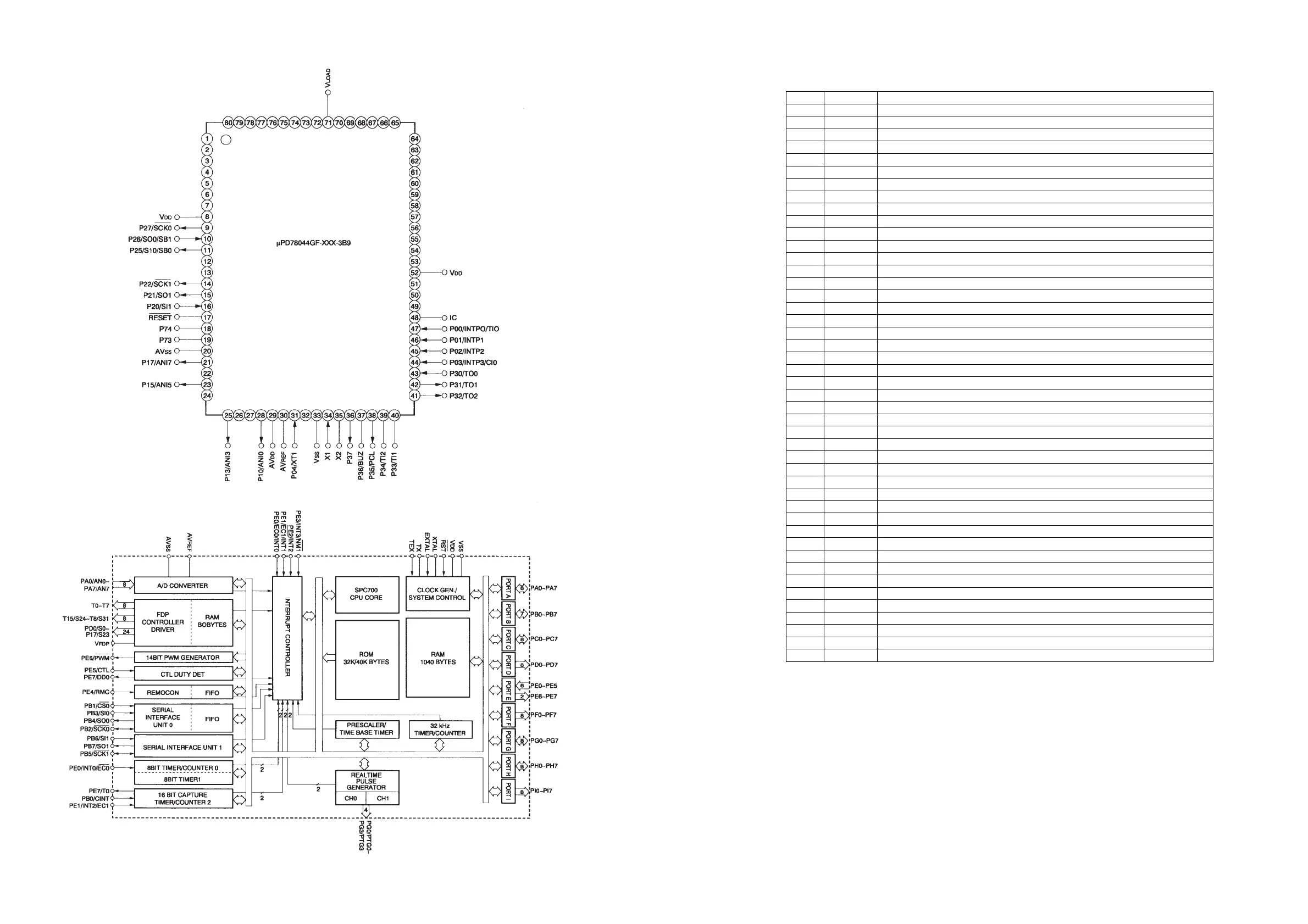
IC801:MPD7804GF-XXX-3B9
1. Pin Configuration
2. Block Diagram
3. Pin Functions
39
 Loading...