7. ALIGNMENT PROCEDURES
TUNER
1.Equipment Required
AM Standard Signal Generator (AM SSG) Audio Generator
Oscilloscope Distortion Meter
AC Voltmeter DC Voltmeter
FM Standard Signal Generator (FM SSG) Frequency Counter
Stereo Modulator
Note : Disconnect external FM antenna prior to alignment
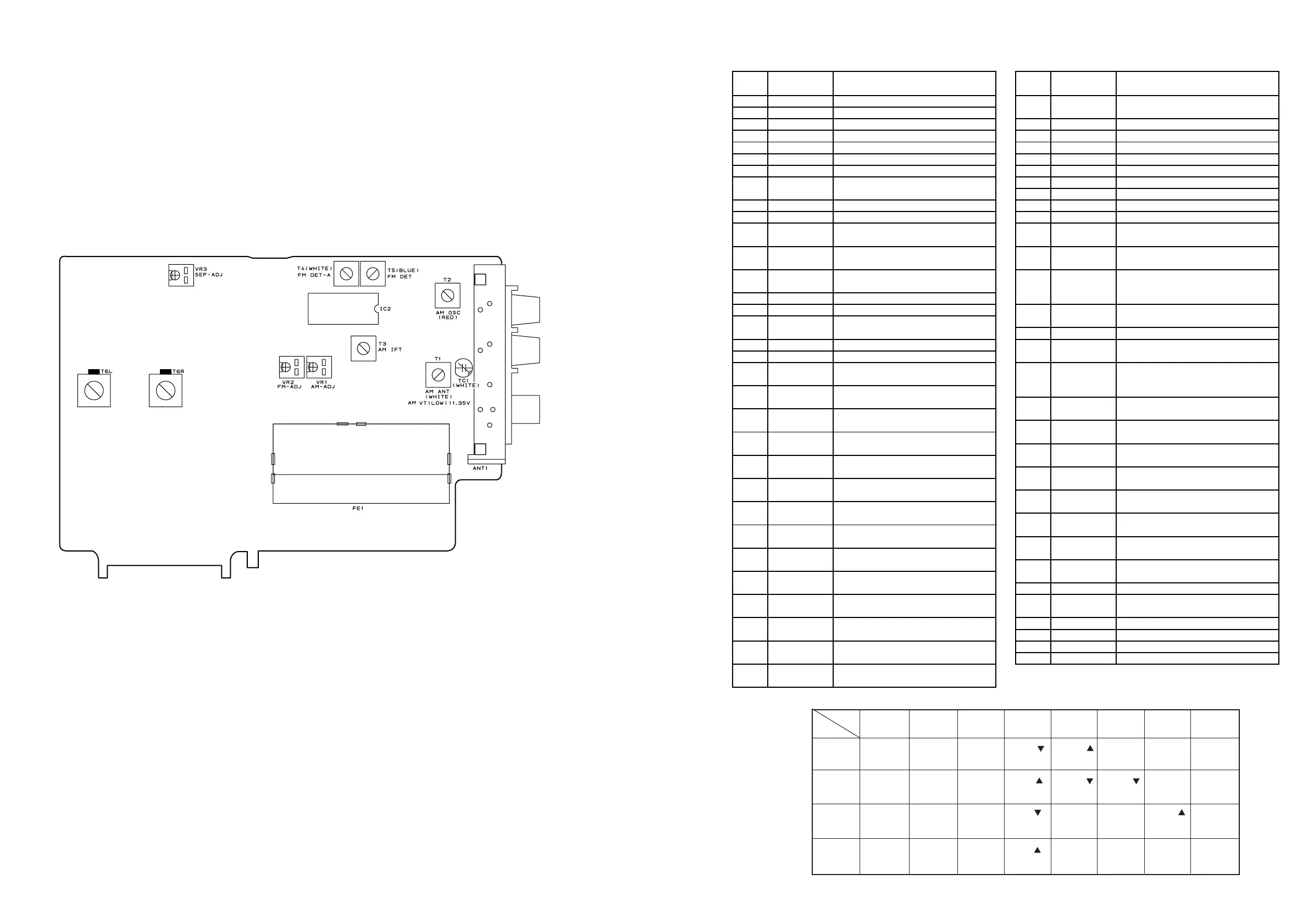
2. Alignment and Test Point
3. Pin Functions
Pin
No.
Symbol Description
Pin
No.
Symbol Description
1 7G~8G Grid si
nal output for FIP. 38 RESET Input for resettin
the CPU.
3 VDD +5V power suppl
.
At "L", it is active.
4 P/D Input for power down. 39 EXTAL Input for 10MHz cr
stal oscillator.
5 VOL. UP Input for main volume up. 40 XTAL Output for 10MHz cr
stal oscillator.
6 RDS CLK CLOCK si
nal output for TDA7330. 41 G Ground.
7 VOL. DOWN Input for main volume down. 42 Not used!
8 RMC Input for remocon data. 43 G Ground.
9 RDS OPTION Input to select RDS or non-RDS. 44 VDD +5V power suppl
.
At "H", RDS is selected.
45 VFDF -30V power suppl
for FIP.
10~11 Not used! 46 4094CE LC7536 CHIP ENABLE
12 7536DATA DATA si
nal output for LC7536
FRONT VR
.
13 7536CLK CLOCK signal output for LC7536 47
7822ST
7821CE
Chip enable signal output to
LC7821 and LC7822.
14 DATA DATA si
nal output for 48 7001CE Chip enable si
nal output to
LC7821 and LC7822. LM7001.
15 CLK CLOCK si
nal output for 49 7536CE2 Chip enable si
nal output to
LC7821 and LC7822. LC7536.
Center, rear and woofer
16~19 KEY IN1~4 Data input for ke
scan. CH. electric vol.
20 RDS. DATA Input for RDS data of TDA7330. 50 DSP. RST RESET si
nal output to IC810
21 PROTECT Input for detectin
"PROTECTION"
uPD78044, pin 17
.
condition. 51 ST-BY Not used!
22 7001. DATA DATA si
nal output for LM7001. 52 TU. MUTE Output for tuner mute.
23 7001. CLK CLOCK si
nal output for LM7001.
At "H", it is active.
24 STEREO Input for detectin
"STEREO" 53 7536CE1 Chip enable si
nal output to
condition. LC7536.
Front channel electric
25 DSP. CLK CLOCK si
nal input from IC810 volume
uPD78044, pin 9
. 54 LED-FRONT Output to drive RF LED.
26 DSP. IN DATA si
nal input from IC810
At "H", it is active.
uPD78044, pin 11
. 55 LED-OPT Output to drive OPTICAL LED.
27 DSP. OUT DATA si
nal output to IC810
At "H", it is active.
uPD78044, pin 10
. 56 LED-MUTE Output to drive MUTE LED.
28 VREF Reference volta
e.
At "H", it is active.
Connected to +5V, Not VDD.
57 LED-COAXIA
Output to drive COAXIAL LED.
29 SPK OFF Input for detectin
"SPEAKER
At "H", it is active.
SWITCH IS OFF" condition. 58 LED-MID Output to drive MIDNIGHT LED.
30 S. MUTE Output for surround channel mute.
At "H", it is active.
At "H", it is active.
59
ED-WOOFE
Output to drive WOOFER LED.
31 F. MUTE Output for front channel mute.
At "H", it is active.
At "H", it is active.
60 LED-RF Output to drive RF LED.
32 AMP MUTE Output for main mute.
At "H", it is active.
At "H", it is active.
61 LED-ST/BY Output to drive stand b
LED.
33 C. MUTE Output for center channel mute.
At "H", it is active.
At "H", it is active.
62~65 P1~P4 Se
ment si
nal output for FIP.
34 W. MUTE Output for subwoofer mute. 66~73 P5~P12 Se
ment si
nal output for FIPand
At "H", it is active.
data output for ke
scan.
35 TUNED Input for detectin
"TUNED" 74~88 P13~P27 Se
ment si
nal output for FIP.
condition.
At "L", it is active.
89 VDD +5V power suppl
.
36 STEP Input for selectin
the fre
uenc
90~94 P28~P32 Se
ment si
nal output for FIP.
ran
es steps of FM and AM. 95~100 1G~6G Grid si
nal output for FIP.
37 VSS Tis pin provides the
round
potential.
4. Key Matrix
KEY IN2 VCR1 DIGITAL VCR2/DVD DELAY CENTER TUNING FM/AM SEARCH
PIN17 SW321 SW306 SW322 SW336 SW330 SW313 SW328 SW307
KEY IN4 SURROUND MID TAPE1 REAR T. TONE F/P CD
PIN19 SW319 SW304 SW325 SW334 SW332 SW311 SW327
KEY IN3 SLEEP WOOFER AUX REAR CEN-MODE MEMORY TUNING PTY-SEL
PIN18 SW302 SW303 SW324 SW333 SW329 SW310 SW314 SW309
P5 P6 P7 P8 P9 P10 P11 P12
PIN66 PIN67 PIN68 PIN69 PIN70 PIN71 PIN72 PIN73
KEY IN1 STEREO AUX/FRONT LD DELAY CENTER FM MODE TAPE2 DISPLAY
PIN16 SW320 SW305 SW323 SW335 SW331 SW312 SW326 SW308
OUT
IN
37
40