3. AM Alignment
Output of signal generator should not be greater than necessary to obtain an optimum output reading.
Signal generator modulation : 30%
RF Signal frequency : 400 Hz
Switch : Press the BAND button to AM
Step Subject
1 Tuning 520kHz 520KHz DC Volt meter to J22 (TP1) T2 DC 1.32V ±1.35V
Voltage (522kHz) (522kHz) AM OSC(R)
2 Usable 600kHz 600kHz AC voltmeter and T1
sentivity (594kHz) (594kHz) oscilloscope to MW ANT(W) Maximize
1400kHz 1400kHz speaker terminal TC1 audio output
(1404kHz) (1404kHz) of L or R channel
* Feed signal should be fed to loop antenna through the test loop antenna 60 cm distant from
the appliance.
* Repeat the step low and high frequency until no further improvement occurs.
3 IF 1000kHz 1000kHz AC voltmeter and T3 Maximize
(999kHz) (999kHz) oscilloscope to speaker AM IFT audio output
terminal of L or R channel
4 Tuned 1000kHz (999kHz) 1000kHz VR1 "Tuned" flag in
Level 800µV/m (999kHz) the FL display
light on
4. FM Alignment
Output of signal generator should not be greater than necessary to obtain an optimum output reading.
Signal generator deviation : USA/Canada/Korea : 75kHz, Europe : 40kHz
RF Signal frequency : 1kHz
Switch : Press the BAND button to FM and MODE button to MONO.
Step Subject
1 Tuning 98.1MHz 98.1MHz DC Volt meter T4 Zero reading on
Band Width (98MHz) (98MHz) to R26 (PCB1) DC Volt meter
2 THD 98.1MHz 98.1MHz Distortion meter to T5 Minimize
(98MHz) (98MHz) TAPE OUT jack distortion
of L or R channel
3 Tuned 98.1MHz (98.1MHz) 98.1MHz VR2 "Tuned" flag in the
Level SSG output level : (98MHz) FL display light on
10µV/m
Signal
Generator
Frequency
Set
Frequency
Setting
Equipment
Connection
Adjustment
Point
Adjust for
Signal
Generator
Frequency
Set
Frequency
Setting
Equipment
Connection
Adjustment
Point
Adjust for
41
5. MPX Alignment
Signal generator frequency : 98 MHz
Signal generator deviation : USA : 75kHz, Europe : 40kHz
RF Signal frequency : 1kHz
Signal generator outut level : 1000µV/m
Connect signal generator to FM antenna terminal through FM dummy antenna (75Ω )
Switch : Press the BAND button to FM and the FM MODE button to STEREO
Step Subject
1 Seperation 8% Modulation pilot on AC voltmeter to VR3 Set AC voltmeter
R → L speaker terminal to 0 dB
of R channel
AC voltmeter to AC voltmeter
speaker terminal reading should be
of L channel at least 40 dB below
2 Seperation 8% Modulation Pilot on AC voltmeter to VR3 Set AC voltmeter
L → R speaker terminal to 0 dB
of L channel
AC voltmeter to AC voltmeter
speaker terminal reading should be
of R channel at least 40 dB below
If you could not obtain -40dB readings in steps 1 and 2, readjust VR3 until you obtain -40dB readings.
Norminal is -45dB. (Europe : Nominal -42dB, Limit -37 dB)
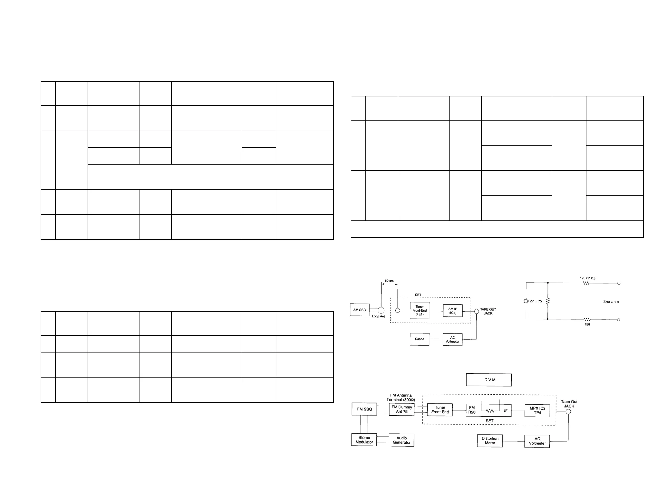
6. Equipment Connection
6-1. AM Alignment Connection 6-2. FM Dummy Antenna
4-3. FM RF/IF and MPX Alignment Connection
Signal
Generator
Frequency
Set
Frequency
Setting
Equipment
Connection
Adjustment
Point
Adjust for
42