63
Differential Signal Data Pins
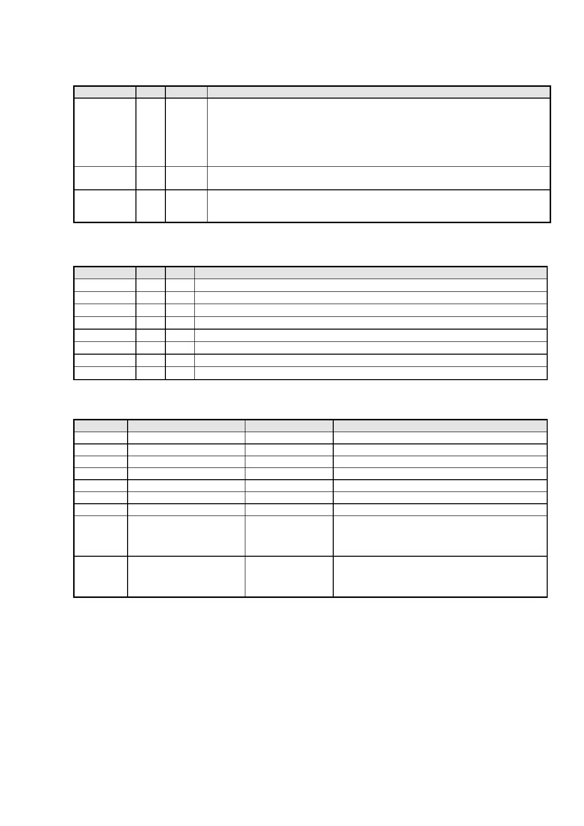
Pin Name Pin # Type Description
TX0+
TX0-
TX1+
TX1-
TX2+
TX2-
40
39
43
42
46
45
Analog
Analog
Analog
Analog
Analog
Analog
TMDS Low Voltage Differential Signal input data pairs.
These pins are tri-stated when PD is asserted.
TXC+
TXC-
35
34
Analog
Analog
TMDS Low Voltage Differential Signal input clock pair.
These pins are tri-stated when PD is asserted.
EXT_SWING 32 Analog Voltage Swing Adjust. A resistor should tie this pin to AVCC. This resistor determines the
amplitude of the voltage swing. A 510Ω resistor is recommended for remote display
applications. For notebook computers, 680Ω is recommended.
Reserved Pins
Pin Name Pin # Type Description
RSVD 20 In
Reserved. Must be tied HIGH for normal operation.
RSVD 21 In
Reserved. Must be tied LOW for normal operation.
RSVD 22 In
Reserved. Must be tied HIGH for normal operation.
RSVD 23 In
Reserved. Must be tied HIGH for normal operation.
RSVD 27 In
Reserved. Must be tied HIGH for normal operation.
RSVD 28 In
Reserved. Must be tied HIGH for normal operation.
RSVD 29 In
Reserved. Must be tied HIGH for normal operation.
RSVD 87 In
Reserved. Must be tied HIGH for normal operation.
Power and Ground Pins
Pin Name Pin # Type Description
VCC 8,30,56,88 Power Digital Core VCC, must be set to 3.3V.
GND 7,31,57,67,79,89 Ground Digital Core GND.
IVCC 17,66,81,98 Power Input VCC, must be set to 3.3V.
AVCC 36,38,44 Power Analog VCC must be set to 3.3V.
AGND 33,37,41,47 Ground Analog GND.
PVCC1 18 Power Primary PLL Analog VCC must be set to 3.3V.
PVCC2 85 Power Filter PLL Analog VCC must be set to 3.3V.
PGND1 19 Ground PLL Analog GND. PGND1 should not be directly
connected to PGND2 before being connected to the
GROUND plane. They should be connected
individually to the GROUND plane.
PGND2 86 Ground PLL Analog GND. PGND2 should not be directly
connected to PGND1 before being connected to the
GROUND plane. They should be connected
individually to the GROUND plane.
IC16 (DVI PCB) : SiI 160