STEP
4:
Hold the
air
pate in the left hand as shown it1 Figure
I
1
TTEP
5:
Insert the handle into the case as shown in Figure 12.
dove the air gate assentbly forward into position U~ke sure the
handle extends through the vertical slot in the front
fnn~e
side
(See Figure
46,
Page
19).
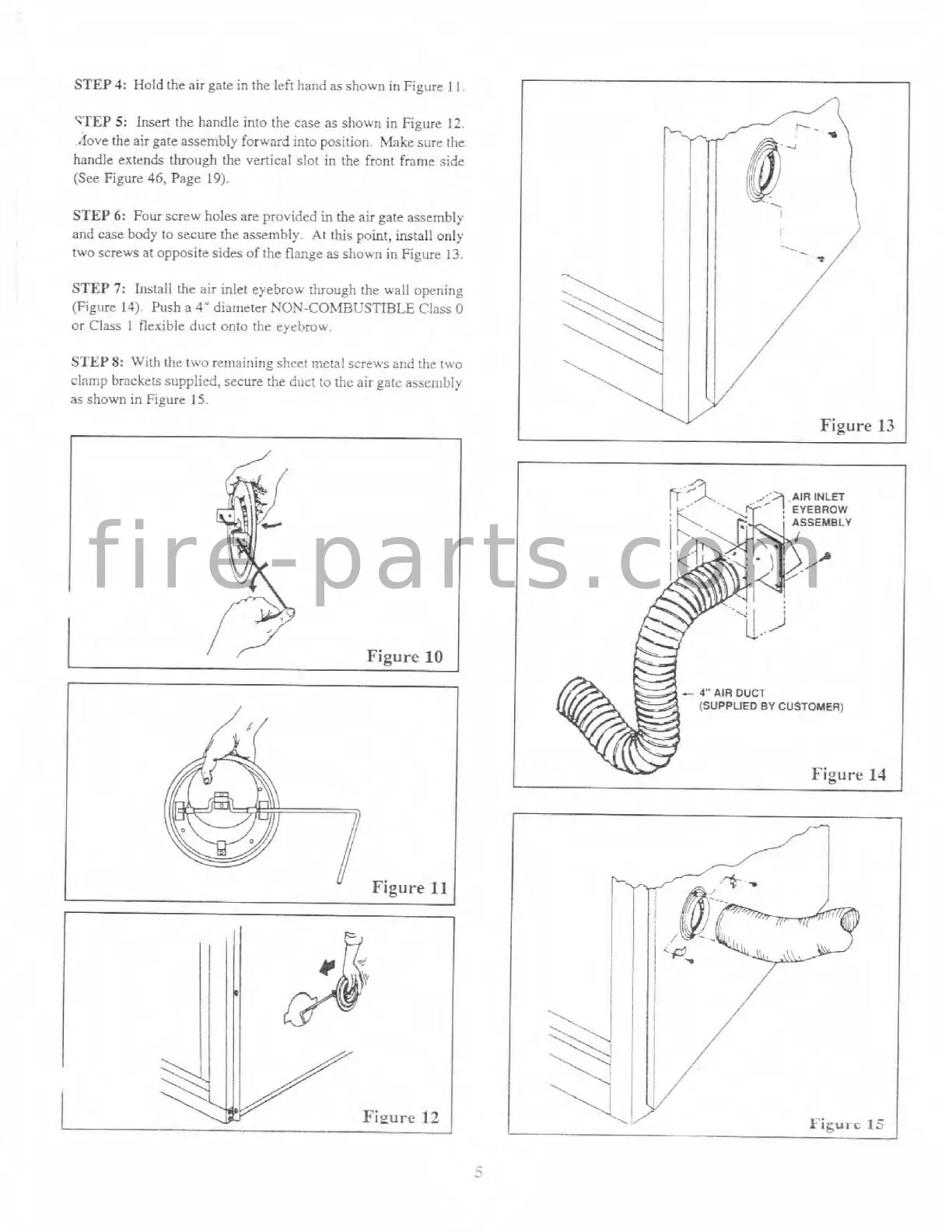
STEP
6:
Four screw holes are provided in the air gate assembly
and case body to secure the assembly At this point, install only
two screws at opposite sides
of
the flange as shown
in
Figure
13.
STEP
7:
Install the air inlet eyebrow through the wall opening
(Figure
14)
Push a
4"
diameter
NON-COMBC'STIBLE
Class
0
or Class
1
flexible duct onto the eyebrow.
STEP
8:
With the two rernainirlg shcct mctnl screu's arid the two
clamp brackets
supplied,
secure the dirct to the air gate assembly
as
shown in Figure
15.
f i r e - p a r t s . c o m