STEP
6:
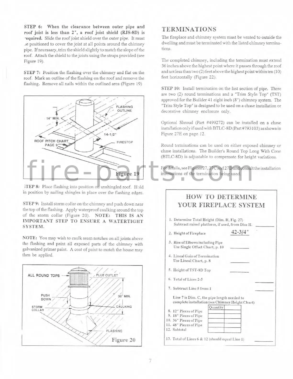
When the clearance between outer pipe and
roof joist
is
less than
2",
a roof joist shield
(RJS-8D)
is
wequired. Slide the roof joist shield over the outer pipe. It must
,e positioned to cover the joist at all points around the chinmey
pipe. Ifnecessary, trirntliesl~ield slightly to niatch the slopeof the
roof. Attach the shield to the joists using the straps providrd (see
Figure 19).
STEP
7:
Position the flashing over the chinmey and flat
011
the
roof. Mark an outline of the flad~ing on the roof and remove the
flashing. Remove all nails within the outlined area (Figure 19)
I
-
Figure
19
1
XEP
8:
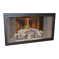
Placc flashing into positioi~ on irnshinglcd roof.
H
,Id
in position by nailin_e shin~lcs in place over the flashing edges.
STEP9:
Install storm collar
OII
tlic chimney and push down near
thr top of the flashing. Apply waterproof
caullu~~g around the top
of the storm collar (Figure
20).
NOTE: THIS IS AN
13,fPORTANT STEP TO ENSURE
A
WATERTIGHT
SYSTEXI.
NOTE:
You
may
wish to caulk seam notches on all joints above
the flashing and paint all exposed parts of
tlie chimney with
galvanized primer
paint.
A
coat of paint to match the house may
then be applied.
/
STORM
___.~
TERMINATIOSS
The
tireplace and ciiirriney systrrrl must be vented to outside the
dwelling
and must be teirninatecl with the listed chimney tennina-
tioris.
Ttlz
completed
cl~irtmcy, inclitding the termination must extend
36
incl~es above the highest point where it passes throlrgh the roof
and
notless than two (2) fcet above the highestpointwithio ten
(10)
feet horizontally (Figure
221,
STEP
10:
Install ternlinatior~ on the last section of pipe. There
are two
(2)
round tern~inations and a "Trim Style Top"
(TS?')
approved for the Builder
4
1
sight inch
(8")
chinlney system. The
"Trim Style Top" is designed to he used on
a
chase installation or
decorative chimney enclosure only.
Optional Shroud (Part
W99272) can be installed on
a
chasc
instnlliltior~ only if
used
with RTI,C-RD (Part '1793 103) asshown
i~r
Figure
27E
on page
12.
Rollrld t;:rn>inations can bc used on either exposed chimney or
chase installations.
The Buildrh Round Top Long With Cone
(BTLC-8D) is adjustable to compcnsatr for height variations.
Fordctails,sceFigures27,27Cand27Dat1dconsulltheinstallation
instructions of the ternlir~;~tion tieing nsed.
I
HOW
TO DETERMINE
I
YOUR
FIREPLACE
SYSTEM
1.
Determine Told Heiglnf (Dim.
H,
Fig.
27)
Sul,tnct rri-e~l plalforrn,
if
urrd,
fvonn
Dim
11.
2.
HrightolFir~~lace
42-314"
3.
RisrofElbo~vr
inclurling
Pipe
Use
Single Offrrt
Ch:~t.l,
p.
10
4.
LineaiGsinuf'Termination
TJse
Lineal Clinrt, p.
8
~
~
~~mpletein~tol~nfion(sreChimncyl%ei~hlCh~~~
12''
Pieces
of
Pipe
18''
Pieces ofPipc
36"
Pieccr nfPipr
48"
Pircrr ofPi1,e
S"lll0l31
f i r e - p a r t s . c o m