4
2015, Marilyn Systems, llc.
Unit Layout
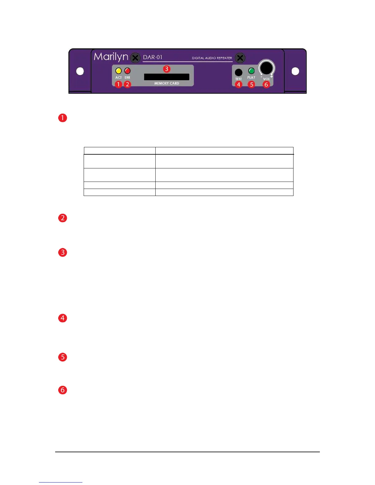
Figure 1 – Front View
ACTivity Indicator
The yellow ACT indicator shows both the current state of the player and any occurring activity.
Indication Function
Slow blink No flash card inserted or no usable configuration
file/media found on the card
Fast blink DAR-01 is reading the configuration file and analyzing
any media present on the flash card
short flash every second Unit is operating normally
½-second flash Indicates input or serial activity
Table 1
ERRor Indicator
The red ERR indicator lights when an issue is present.
MEMORY CARD slot
All sound files and configuration information are stored a SD or SDHC flash memory card. The card is
inserted by gently pushing it into the socket, with the contacts down and towards the DAR-01, until a “click”
is heard. To remove the card, push it in slightly until a “click” is heard. The card is now unlocked and will
be ejected from the socket.
If you wish to prevent removal of the card, an optional guard cover is available.
TEST button
This momentary pushbutton switch provides a user-programmable means of testing the unit. Please refer to
the configuration section for more details.
PLAY LED
The red PLAY indicator lights to indicate that the unit is playing audio
VOLume Potentiometer
This programmable potentiometer provides control over upper and lower limits or can be disabled. Please
refer to the configuration section for more details.