2015, Marilyn Systems, llc.
5
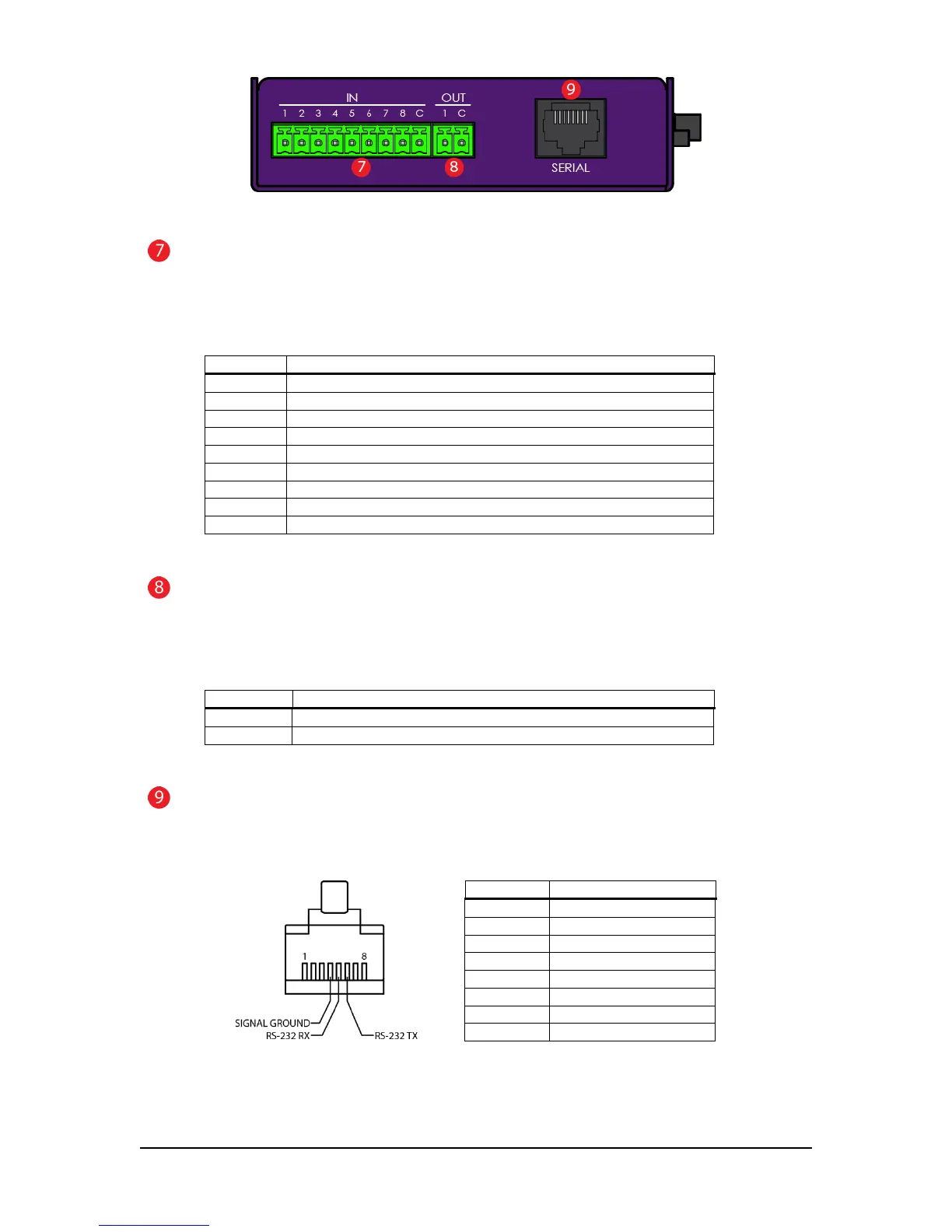
Figure 2 – Left View
INputs Connector
Eight non-polarized, optically-isolated inputs are available for triggering tracks and performing other actions.
The entire group shares a single common. The inputs can accept 12-24VDC and draw a maximum of 10mA.
Please refer to figures 7 & 8 for wiring examples.
Terminal Function
1 Input 1
2 Input 2
3 Input 3
4 Input 4
5 Input 5
6 Input 6
7 Input 7
8 Input 8
C Input Common
Table 2
OUTput Connector
A solid-state relay output is available for various functions. This relay can switch 100mA at 24VDC, enough
to drive a typical electromechanical relay, lamp, or other similar device. Please refer to figures 9 & 10 for
wiring examples.
Terminal Function
C Status output common contact
NO Status output normally-open contact
Table 3
SERIAL Connector
RS-232 port brought out on an EIA-561 compatible RJ-45 jack. See configuration file section for serial port
operating parameters.
Terminal Function
1 NC
2 NC
3 NC
4 Signal Ground
5 DAR-01 Rx
6 DAR-01 Tx
7 Reserved
8 NC
Pin-out (cable-end, connector front) Table 4