6
2015, Marilyn Systems, llc.
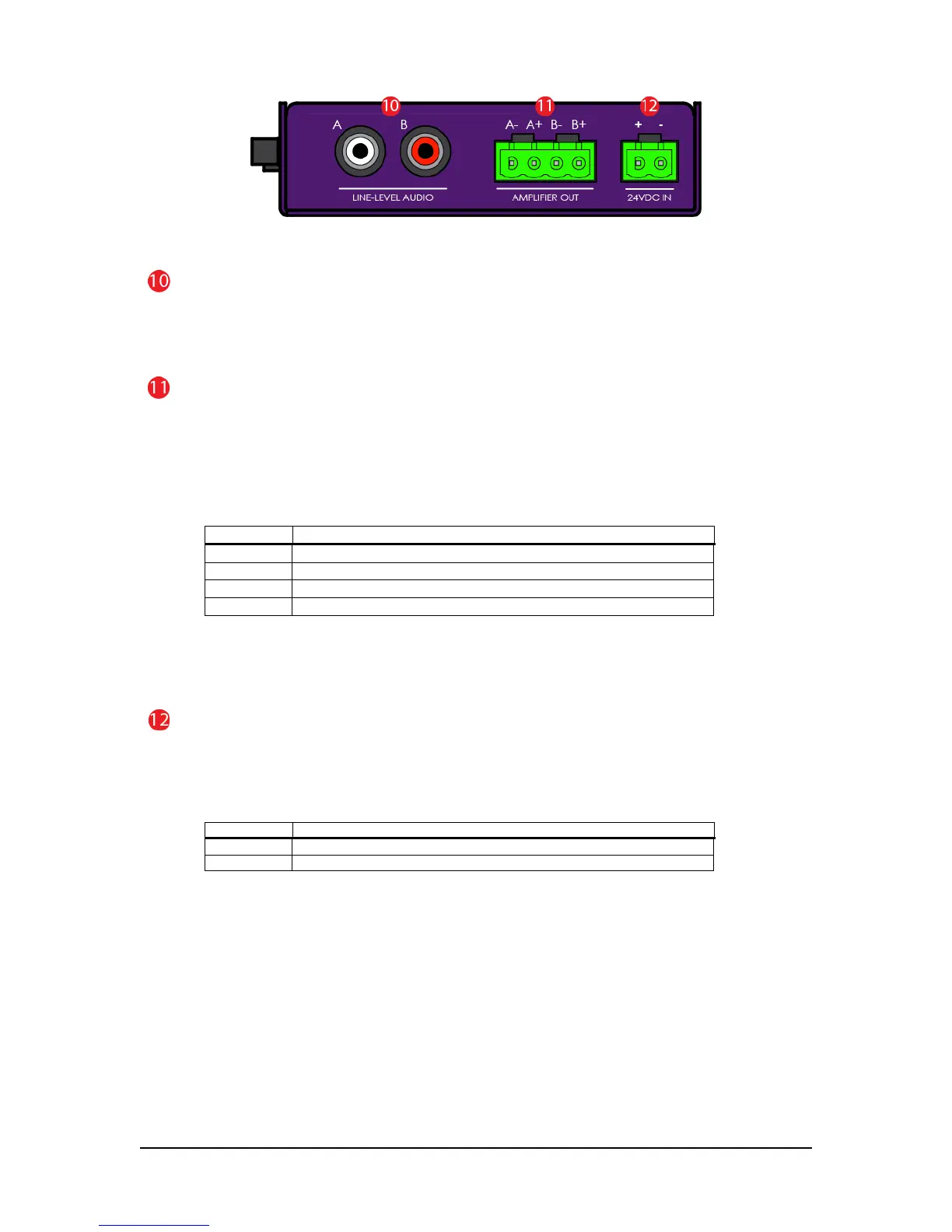
Figure 3 – Right View
LINE-LEVEL AUDIO Jacks
Two RCA, line-level output jacks marked A (left) and B (right) are provided for connection to an external
audio system. These outputs are always active regardless of the state of the amplifier.
AMPLIFIER OUT Connector
A 40W-per-channel, stereo amplifier which can directly drive a 4 to 8-ohm loudspeaker load (see figure 5).
Optionally, the outputs may be paralleled for a single, 80W output by jumping together both positive
terminals and both negative terminals respectively (see figure 6 for a wiring example). PLEASE NOTE that
a mono audio file
must
be used when the outputs are paralleled. The amplifier can be disabled if it will
not be used. Please refer to the configuration information below for more details.
Terminal Function
A- Channel A (left) negative terminal
A+ Channel A (left) positive terminal
B- Channel B (right) negative terminal
B+ Channel B (right) positive terminal
Table 5
If you are upgrading from a rev. b or rev. c DAR-01, please notice that the amplifier output pin-outs
have changed.
24VDC IN Connector
The DAR-01 can operate on a little as 12VDC however for optimal amplifier performance, 24VDC should be
provided. With the amplifier enabled, a minimum 100Watt supply should be used.
Do not
use an
unregulated supply as this could damage the player. See figure 4 for a wiring example.
Table 6