Do you have a question about the Mark Levinson 432 and is the answer not in the manual?
| Input Impedance | 100k ohms |
|---|---|
| Voltage Gain | 26.8dB |
| Power Output | 400W per channel into 8 ohms |
| Frequency Response | 20Hz - 20kHz (±0.1dB) |
| Signal to Noise Ratio | >85dB |
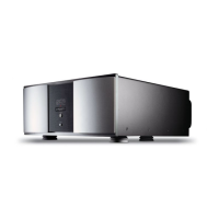
| Type | Stereo Power Amplifier |
Guide for registering the product within the warranty period.
Optimal positioning and airflow requirements for the amplifier.
Details on power needs, warm-up, operating states, and continuous use.
Description of the amplifier's robust power supply components.
Explanation of the balanced input topology and circuit design.
Details on the built-in protection circuits against fault conditions.
Explains the LED behavior indicating operating state and faults.
Operation of the power button for turning the unit on and off.
Controls the transition between standby and sleep modes.
Information regarding lifting and moving the unit using rear handles.
Description of the output terminals for connecting loudspeakers.
Details on connecting unbalanced audio signals via RCA connectors.
Details on connecting balanced audio signals via XLR connectors.
Serial port for software upgrades and external control systems.
Ports for linking Mark Levinson components for control sharing.
Connectors for DC trigger control of power on/off sequences.
Switch to determine response to trigger signals (sleep vs. standby).
Location of the IEC power receptacle for connecting the mains cord.
Guidelines for connecting components using Link or Link2 ports.
Instructions for building custom communication cables for linking.
Process for establishing a communication chain among components.
How linked components share and manage controls.
Steps to diagnose and resolve no audio with a dark indicator LED.
Steps to resolve no audio when the LED is dimly lit (sleep mode).
Steps to resolve no audio when the LED blinks slowly (standby mode).
Steps to resolve no audio with a rapidly blinking LED (power fault).
Steps to resolve no audio with a rapidly blinking LED (signal fault).
Steps to resolve no audio with a rapidly blinking LED (thermal fault).
Steps to resolve no audio when the LED is fully lit (no signal).
Troubleshooting steps for an amplifier that repeatedly powers off.
Final troubleshooting steps and contact information.