21
FX20 INSTALL GUIDE
VERSION 1.6 | APRIL 26, 2024
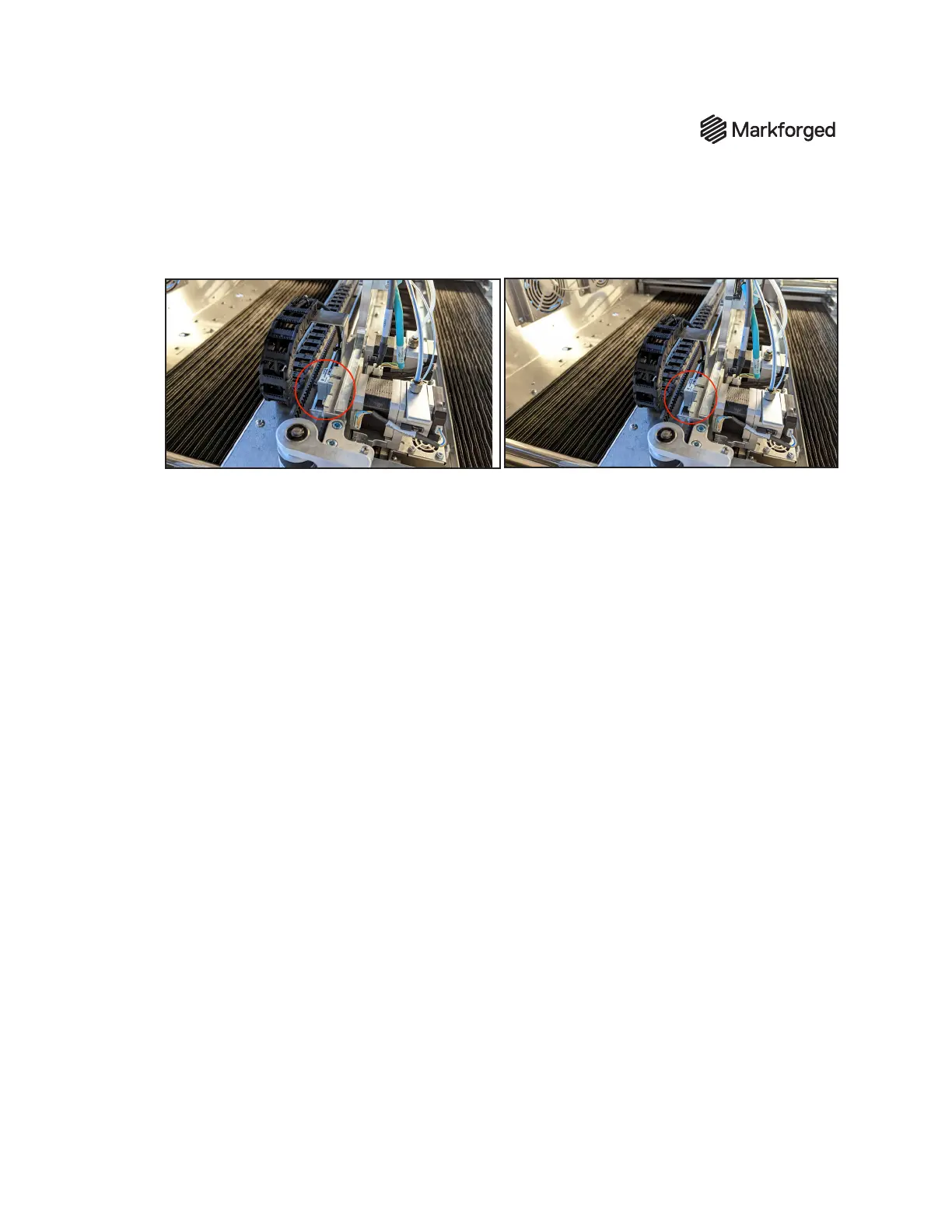
XAXIS ENCODER
1. The X-axis encoder sensor is located behind the print head back plane. Gently move the X-axis
through its full range of motion.
2. If the encoder sensor contacts the encoder strip at any point during this movement, use a 2.5mm
hex driver to loosen the three screws -- but do not remove them. (Note that the screws are not
captive; take care not to let them fall into the bellows.)
3. Raise the encoder sensor slightly, and adjust its orientation by hand until it is aligned parallel with
the encoder strip.
The gap between the sensor and strip must be between 0.25mm and 0.75mm
To
gauge the proper distance between sensor and strip, a piece of paper can be folded over twice (
so
four total layers of paper are being used to set the gap)
and used as a shim. Note: The sensor must
be oriented parallel to the encoder strip.
4. Once the encoder sensor is positioned at the proper height and orientation, fully tighten all three
screws.
5. Move the gantry through the full range of X-axis motion to verify that its movement is unobstructed,
and conrm that the LED indicator light is green through the full range of motion.
6. If the indicator turns red at any point during travel, the encoder gap should be corrected to meet
the spec in Step 3 - take care to ensure that the encoder does not contact the strip. Repeat X-axis
calibration until the indicator light remains green through the full range of gantry motion.