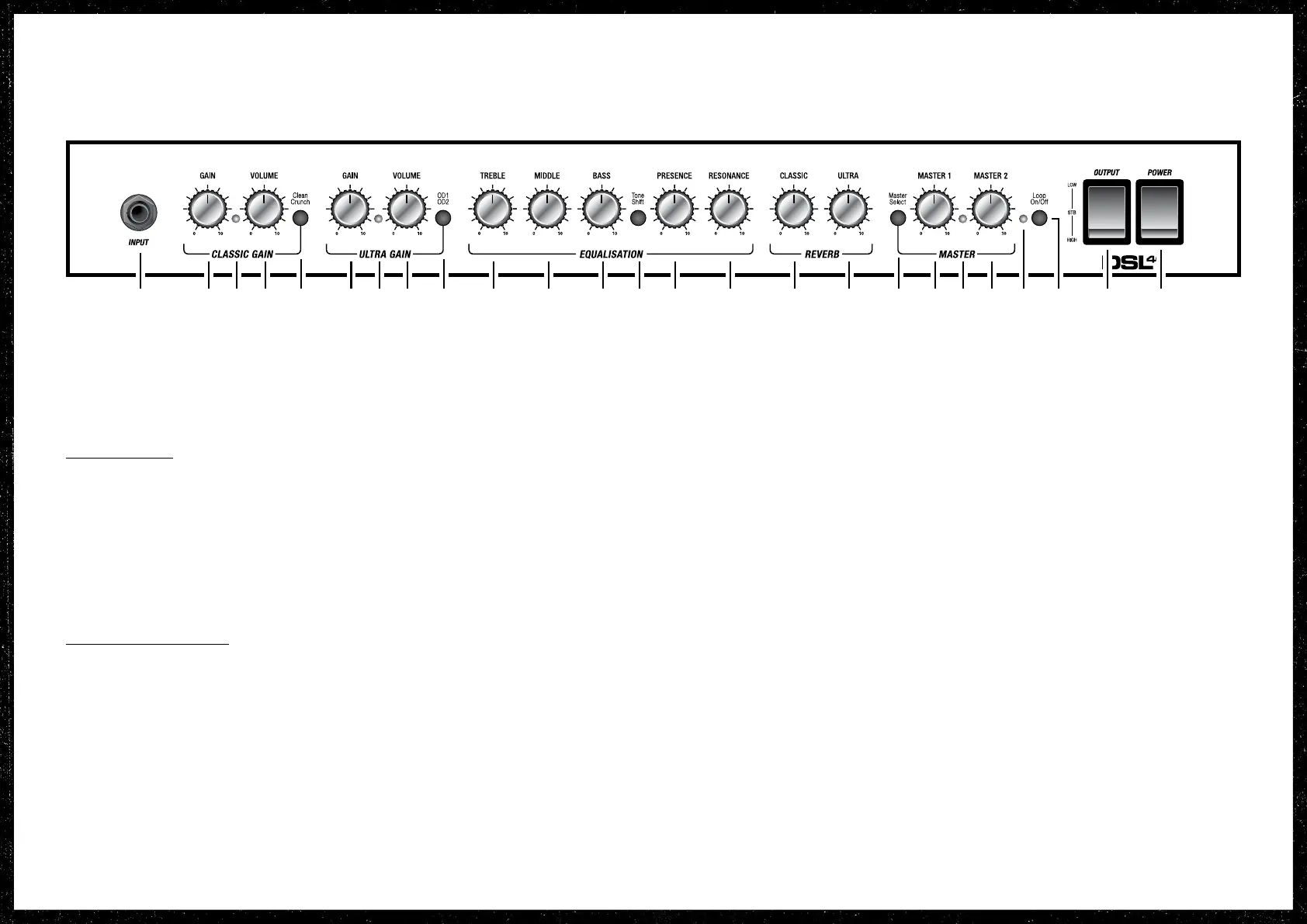
FRONT PANEL FUNCTIONS (CONTINUED)
in your sound. Turning this control
clockwise adds a resonant bass boost,
increasing boom-end. Resonance
is a power-stage funcon and acts
independently of the preamp EQ controls.
REVERB SECTION
16. REVERB CLASSIC
Controls the reverb level of the classic
gain channel.
17. REVERB ULTRA
Controls the reverb level of the ultra gain
channel.
MASTER VOLUME SECTION
18. MASTER SELECT
This switches between master 1 and
master 2.
19. MASTER 1
Controls the overall volume level of the
amplier when selected.
20. MASTER STATUS LED
This LED lights green to indicate that
master 1 is selected and red to indicate
master 2 is selected.
21. MASTER 2
Controls the overall volume level of the
amplier when selected.
22. LOOP STATUS LED
This LED lights red to indicated that the
FX loop is on. It is unlit when the FX loop
o.
23. LOOP ON/OFF
This switch acvates and deacvates the
FX loop
Note: FX loop on/o is footswitchable
using the supplied 2-way footswitch or
the oponal 6-way footswitch.
24. OUTPUT
This three posion rocker switch
combines STB (standby) and HIGH/LOW
output power funcons.
The output stage and power control
for this amplier has been designed to
deliver the opmum tonal performance
at all power levels. The high and low
output funcons allow the user to
choose between two conguraons of
the internal power supply. These two
conguraons give the choice between
two output power levels, but ensure that
the output valves behave in the same
way for both. This means the amplier
can be put into low power mode without
compromising on tone.
HIGH: This is the 100 Wa seng for
the DSL100HR and the 40 Wa seng
for the DSL40CR.
STB (standby): This is used in conjuncon
with the mains POWER switch (Front
Panel Funcon #25). When powering
up, always switch mains power on rst,
leaving the output switch in the STB
(standby) posion. Standby mode should
also be used to mute the amp during
breaks in performances to avoid stress to
the valves of the amplier.
1 2 3 4 5 6 7 8 9 10 11 12 13 14 15 16 17 18 19 20 21 22 23 24 25
LOW: This is the 50 Wa seng for
the DSL100HR and the 20 Wa for the
DSL40CR.
25. POWER
Mains power on/o switch.
13DSL40CR service manual
BOOK-80015-01 | M3390.069
 Loading...