1998-08-03 11Parts Removal and Installation
2.10.2 C
ONFIGURE
XLR
PIN
-
OUT
AND
BOOT
SET
-
TING
JUMPERS
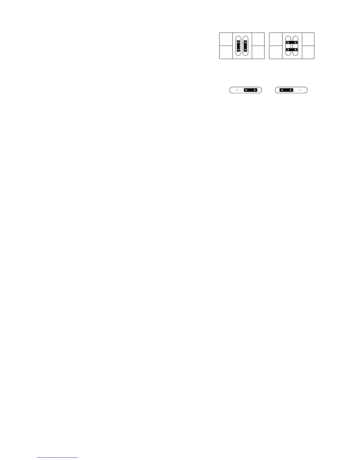
1. Position the jumpers for the desired XLR pin-out on PL
233/234 as shown in Figure 2-5.
2. Position the jumper on PL 121 for the desired boot setting
as shown in Figure 2-5. The hard boot setting is only used
to upload software when the fixture must be set to boot
mode and the control panel does not function. After the
upload, move the jumper back to the normal setting.
2.10.3 I
NSTALL
CIRCUIT
BOARD
1. Before installing a board, make sure the hard boot jumper
and XLR pin-out jumper are configured correctly. See sec-
tion 2.10.2.
2. Plug in connectors at the bottom of the card. See the block diagram in section 8.
3. Plug in the lamp relay wires: mains in (red) to RL 3, ballast in (brown) to RL 4, and ballast out (black) to PL 221.
4. Tuck lamp relay wires under the motor assembly.
5. Guide the circuit board into position and lock by snapping the black pins into their holders.
6. Plug the cables in to the top of the circuit board.
2.11P
AN
ASSEMBLY
2.11.1 R
EMOVE
PAN
ASSEMBLY
1. If removing the pan assembly to replace a pan motor, you may find it easier to remove the yoke from the base.
See procedure 2.3.2.
2. Remove the side profile from back.
3. Remove AC filter.
4. Remove the 6 x 10 mm locking nuts holding the pan assembly to the base.
5. Unplug the 2 wires from the pan reset switch.
6. Unplug the pan sensor cable under the sensor timing wheel and unplug the pan motor cable from the connec-
tion below the sensor module.
7. Remove the assembly.
2.11.2 I
NSTALL
PAN
ASSEMBLY
1. Arrange the circuit board and lamp relay wires neatly in the base.
2. Fasten the transformer wires to the back rail with a wire tie.
3. Position the pan assembly in the base.
4. Fasten the assembly with 6 x 10 mm bolts and lock nuts.
5. Install the AC filter on the pan assembly with the “load” end towards the ballast.
6. Connect the AC filter wires. On the line side, connect the neutral (blue) wire to the top terminal, the live (brown)
wire to the bottom terminal, and ground wire to the case. Similarly, on the load side, connect the blue wire lead-
ing to the capacitor to the top terminal and connect the brown wire to the bottom terminal.
7. Plug in the pan sensor and motor wires.
8. Plug the pan-reset switch wires into the bottom 2 switch contacts.
2.11.3 R
EPLACE
PAN
DRIVE
BELT
1. Remove the yoke from the base. See procedure 2.3.2.
2. Remove the pan sensor module.