1998-08-03 17Adjustment
3.11O
PTIMIZING
L
AMP
A
LIGNMENT
1. Disconnect the fixture from AC power supply and allow the lamp to cool.
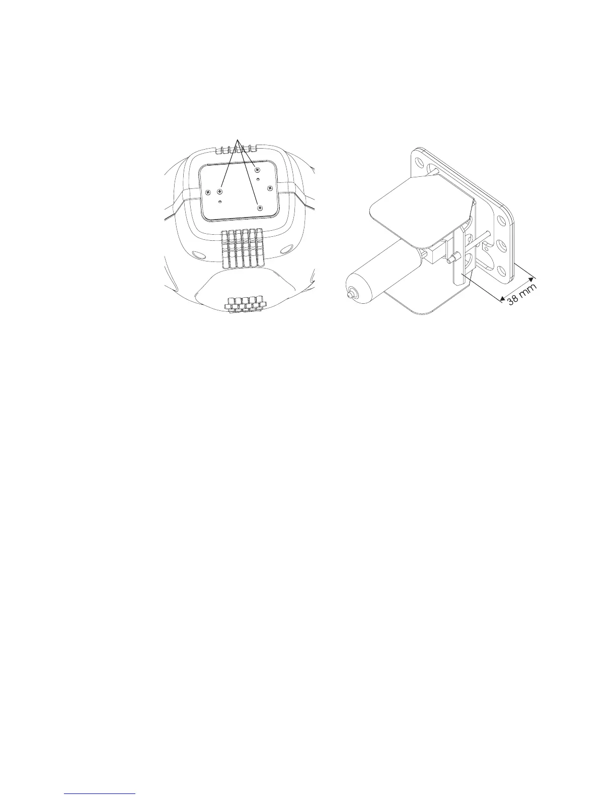
2. Make a preliminary adjustment: remove the lamp-socket assembly and use the 3 lamp adjustment screws to
position the lamp-socket plate a distance of 38 mm (1.5”) from the access plate (outside measurement).
3. Replace the lamp-socket assembly.
4. Switch on the MAC 500 and wait until the reset has finished.
5. Using either a controller or the control panel, turn on the lamp and focus the light on a flat surface.
6. Center the hot-spot (the brightest part of the image) by using the three adjustment screws. Turn one screw at a
time to drag the hot-spot diagonally across the projected image. If you cannot detect a hot-spot, adjust the lamp
until you achieve an even distribution of the light.
7. If there is too much hot spot or a dark spot in the center of the beam, you can further adjust the lamp by turning
all three adjustment screws a quarter-turn clockwise, making sure that the hot-spot remains centered. If the
result is an improvement then repeat this procedure until there is no more improvement. If the result is worse,
then turn the adjustment screws a quarter-turn counterclockwise and observe the result. Proceed this way as
long as the result is an improvement.
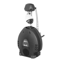
lamp adjustment screws