12
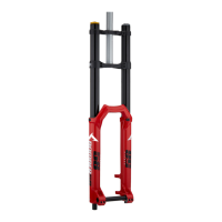
ASSEMBLY OF FRONT WHEEL TO “QR 20” FORKS
Make sure the quick release bushings (ref. 7) are
centered to the recesses in the sliders.
Lock the quick release lever (ref. 8) and make
sure the bushings (ref. 7) are properly seated in
the sliders on both sides.
W
ARNING: these sliders are specifically de-
signed to fit this type of hub. Do not use any
hub design other than that specified here, as this
would not ensure proper fastening of the wheel
and may lead to breakdown of the assembly
components.
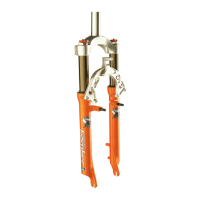
ASSEMBLY OF FRONT WHEEL TO MONSTER T FORK
• Insert the complete wheel assembly between
the sliders and fit the wheel shaft (ref. 9) into
the slider that accommodates the wheel shaft
pinch bolt (ref. 10) from the right hand side.
• Rotate wheel shaft clockwise to start it into the
LH slider.
• Tighten the wheel shaft (ref. 9) onto the LH
slider turning it counterclockwise from the
opposite end with an 8-mm Allen wrench.
• Tighten the wheel shaft to the specified torque.
• Compress the fork several times so the sliders
will become properly seated onto wheel shaft.
Lock the bolt (ref. 10) in the RH lug to the
specified torque.
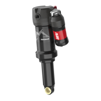
DISC BRAKE SYSTEM ASSEMBLY
Assembling the brake caliper onto the slider is a
very delicate operation that should be carried out
with extreme care. Improper assembly might
overstress the caliper supports which might break.
This system should be installed by specialized
technicians in a position to fully understand and
properly follow the instructions given by the
manufacturer.
FISSAGGIO RUOTA SU FORCELLE “QR 20”
Verificate che le bussole (Rif. 7) di appoggio dello
sgancio risultino centrate nella sede incassata dei
foderi.
Bloccate la levetta (Rif. 8) dello sgancio rapido e
verificate, su entrambi i lati, il perfetto assesta-
mento delle bussole (Rif. 7) all’interno delle sedi
dei foderi.
A
TTENZIONE: la particolare forma dei foderi
è stata progettata per supportare un moz-
zo del tipo raffigurato. Per evitare possibili
allentamenti del sistema di fissaggio della ruota
o rottura degli elementi interessati, evitare asso-
lutamente il montaggio di altri tipi di mozzi.
FISSAGGIO RUOTA SU FORCELLA MONSTER T
• Inserite la ruota completa tra i foderi ed infi-
late dal lato destro il perno ruota (Rif. 9) nel
fodero provvisto di vite (Rif. 10) di bloccaggio
perno.
• Ruotate il perno in senso orario per impuntarlo
sul fodero sinistro.
• Operando sul lato opposto con una chiave per
esagoni interni da 8 mm, avvitate in senso
antiorario il perno ruota (Rif. 9) sul fodero
sinistro.
• Bloccatelo alla coppia prescritta.
• Fate compiere alla forcella qualche affondamento
per assestare i foderi sul perno ruota quindi
bloccate la vite (Rif. 10) sul portaruota destro
alla coppia prescritta.
INSTALLAZIONE DELL’IMPIANTO FRENO A DISCO
Il montaggio della pinza freno sul fodero rappre-
senta una operazione molto delicata che deve
essere eseguita con molta attenzione.
Una installazione errata può generare delle ten-
sioni e provocare la rottura dei supporti pinza.
Fate installare l’impianto da personale specializ-
zato in grado di interpretare ed eseguire corretta-
mente le istruzioni fornite dalla casa costruttrice
dell’impianto stesso.
 Loading...