Do you have a question about the Masibus 5040 and is the answer not in the manual?
Introductory text from the manufacturer.
Important information regarding manual updates and accuracy.
List of registered trademarks mentioned in the manual.
Instructions to verify received product and accessories.
Table detailing model and configuration options.
Items included with the product.
Essential safety guidelines for using the instrument.
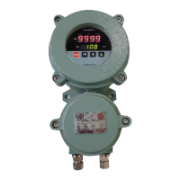
Guidelines for selecting a suitable location for controller installation.
Technical drawings showing physical size and panel mounting requirements.
Detailed instructions and precautions for electrical wiring.
Technical specifications for various input types supported by the controller.
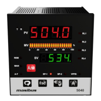
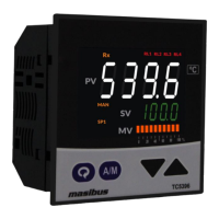
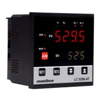
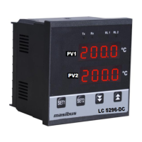
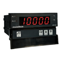
Description of front panel displays, indicators, and keys.
Overview of the different output types available on the controller.
Information on communication interfaces, protocols, and baud rates.
Specifications for the controller's power requirements and isolation.
Physical dimensions, weight, material, and accessories.
Operating and storage conditions for the controller.
Diagram showing internal wiring connections on the backplate.
Wiring diagram for connecting a 2-wire transmitter with power supply.
Wiring diagram for valve position feedback and interlock relays.
Explanation of the function of each key on the front panel.
Parameters viewable or changeable during normal operation.
Procedure for setting target set points for the controller.
Control parameter configuration, including auto-tune and PID values.
Alarm and digital output settings configuration.
Functional parameter configuration, including input types and scaling.
Further functional parameter configuration, including remote input and communication settings.
SELECT Display settings for customizing the displayed parameters.
Configuring DI-1 for Set Point 1 or Set Point 2 selection.
Configuring DI-2 for Auto/Manual mode switching.
Configuring DI-3 for Local/Remote set point selection.
Configuring DI-4 for Run/Stop control selection.
Guide for adjusting PID parameters (PB, TI, TD) to optimize control.
Table showing how relays can be configured for different output types.
Procedure to calibrate ambient temperature measurement for thermocouple inputs.
Process for calibrating PV sensor input for various input types.
Calibration steps for the remote set point input.
Calibration process for the valve position feedback signal.
Calibration procedure for retransmission output signals.
Calibration procedure for the current output signal.
Explanation of Modbus function codes used for communication.
Meanings of Modbus exception response codes.
List of Modbus parameters with their addresses and types.
Step-by-step guide to diagnose and resolve common instrument issues.
How PV input status is displayed during burnout conditions.
Display messages for Remote Set Point burnout conditions.
Display messages for Valve Position Feedback open conditions.
Table detailing retransmission output behavior for various conditions.
Table detailing control output behavior for various conditions.
Instructions for selecting digital input and retransmission output types via jumpers.
| Control Action | PID, On/Off |
|---|---|
| Display | Dual 4-digit LED |
| Accuracy | ±0.25% of FS |
| Output Current | 4-20 mA |
| Communication Protocol | Modbus RTU |
| Communication | RS485 |
| Power Supply | 85-265 VAC, 50/60 Hz |
| Input Voltage | 0-10 V |
| Protection Class | IP65 |
| Input Type | Thermocouple, RTD |
| Output | Relay, SSR |