Doc.Ref. No. m83B/QG/101 Issue No.:00 Page 1 of 2
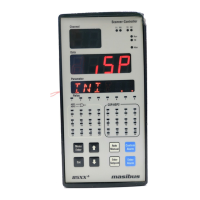
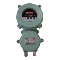
85XX+ Scanner/DAQ
+ 0.1% of instrument
range + 1 digit
RESOLUTION
TC(E,J,K,T)/RTD/CU53/NI120:
TC(B,R,S,N):
LINEAR:
ADC: 17 bits
0.1C
1C
1 Count
DIN (ITS-90) for
Thermocouple and RTD
SAMPLING PERIOD PER
INPUT
50 ms for TC and Linear
Input and 100 ms for
RTD
>1 MΩ for RTD/Voltage
inputs, 250 Ω for
current Input
ALLOWABLE WIRING
RESISTANCE FOR RTD
Maximum 15 ohms/wire
(Conductor resistance
between three wires
should be equal).
Digital Input Specification (Optional)*
* With Digital Input, CE marking is not applicable/valid
Digital Output- Relay
Alarm or trip or control or
watchdog output
NUMBER OF RELAY
OPERATION
Digital Output- Open Collector (Optional)
Alarm or trip or control or
watchdog output
transistor open collector
output selection)
Analog Output- Analog Output (Optional)*
0-20 mA, 4-20 mA or 0-5 V,
1-5 V, 0-10 V DC
For current o/p, 550Ω Max.
For Voltage o/p, 3000Ω Min.
* With Analog Output, CE marking is not applicable/valid.
Programming and Setting
8-keys tactile membrane
keypad
All Configurable parameters can
be set through PC Based
software
Non-volatile, restored after
power loss
Communication Specification
NO. OF COMMUNICATION
PORT
2-RS485(COM-1 and
COM-2) . COM2 is
Optional
MODBUS RTU. All
parameters are
Configurable through
MODBUS Protocol.
PROFIBUS Communication (Optional) *
9600, 19.2K, 44.45K, 93.75K,
187.5K, 500K, 1.5M, 12M bps
Configurable through Configuration
Software (0 to 125 Only)
Multi-drop up to 31 modules, Plus
a host, without a repeater
Up to 125 modules plus a host if
four repeaters are used
Up to 1200 meters without a
repeater using Type A wire
1200m @ 115Kbps or less
1000m @ 187.5Kbps
400m @ 500Kbps
200m @ 1.5Mbps
100m @ 12Mbps
* With Profibus communi. , CE marking is not applicable
HMI Interface (Optional)*
NO. OF COMMUNICATION
PORT
Network Connectivity (Optional)
NO. OF COMMUNICATION
PORT
Periodic Logging sampling
time
For retrieving logged
data only
Max. USB storage device
size
USB Mass storage device
format
USB fetched data file format
USB data retrieving option
Full Data Fetch
Fetch Data by time
*With USB port, CE marking is not applicable/valid.
Display Specification
2-digits, 7-segment, Green , 0.56”
character height
4-digits, 7-segment, Red, 0.56’’
character height
6-digits, 16-segment Alphanumeric,
Orange LEDs, 0.3” character height
24-Red LEDs for Alarm, 24-Orange
LEDs Control Output, 8-Green LEDs for
Relay, 1-Red LED for Manual mode, 1-
Green for Run mode,1-Red for Fault,
2-Green(Rx) & 2-Red(Tx) for
Communication
Environmental Specification:
30% to 95% RH
(Non-Condensing)
Power Supply Specification
85-265VAC-50/60Hz /
100-300VDC or 18-36VDC
Max. 16 VA (85-265 VAC)
and Max. 8 VA (18-36
VDC)
Isolations (Withstanding Voltage)
Between primary terminals* and secondary
terminals**: 1500VAC for 1 minute
Between secondary terminals: 500V AC for 1
minute
* Primary terminals indicate power terminals and
relay output terminals
** Secondary terminals indicate analog input signals,
Digital Contact output terminals, communication
terminals and Ethernet N/W terminal
Insulation Resistance: 20MΩ or more at 500 V DC
Signal Isolation Specifications
Isolated from other ip/op
terminals and internal circuit
Not isolated from other analog
i/p terminals & the internal
circuit. But isolated from other
ip/op terminals.
Isolated from other ip/op
terminals and internal circuit
Isolated from other ip/op
terminals and internal circuit
Isolated between contact o/p
terminals & from other ip/op
terminals and internal circuit
Isolated from other ip/op
terminals and internal circuit
MAXIMUM
ALLOWABLE
INPUT
VOLTAGE