Do you have a question about the Masibus LC5296-XP and is the answer not in the manual?
Introductory text thanking the user for purchasing the FLP series.
States that manual contents are subject to change without notice due to continuous improvements.
Lists product names as trademarks of Masibus and Adobe Systems Incorporated.
Instructions for verifying product contents upon delivery to ensure no parts are missing or damaged.
Provides information to prevent possible harm to users and damage to property during product use.
Details the types and specifications of analog inputs supported by the controller.
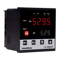
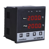
Describes the display specifications and key functions on the controller's front panel.
Outlines the available output types like Relay, SSR, and Linear.
Specifies communication interface, protocol, and baud rates.
Details standard and optional power supply requirements and consumption.
Lists operating temperature, humidity, and warm-up time requirements.
Highlights unique features like Input Scalability and Ramp Soak Function.
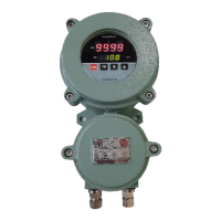
Provides mechanical details and dimensions for the single compartment enclosure.
Details mechanical specifications and dimensions for the dual compartment enclosure.
Illustrates terminal connections for the single compartment enclosure.
Illustrates terminal connections for the dual compartment enclosure.
Provides essential guidelines and safety notes for wiring the controller.
Describes the layout and function of front panel components like PV, SV, and keys.
The primary operational display and entry point for the controller.
Password entry section for accessing configuration settings.
Section dedicated to adjusting PID tuning parameters.
Configuration menu for setting up controller parameters.
Describes parameters viewable or changeable during runtime.
Details how to set and modify control and alarm set points.
Explains the auto-tuning process for PID control.
Covers parameters for configuring input type, calibration, and other settings.
Explains the procedure for calibrating the instrument's zero and span.
Settings related to set point parameters, often dependent on configuration.
Visual representation of navigating configuration settings like Input Type.
The primary operational display and entry point for the controller.
Configuration menu for setting up controller parameters.
Calibration menu for zero, span, and retransmission adjustments.
Describes parameters viewable or changeable during runtime.
Details how to set and modify control and alarm set points.
Covers parameters for configuring input type, calibration, and other settings.
Parameter for Ambient temperature adjustment.
Parameter for Zero calibration.
Parameter for Span calibration.
Parameter for Retransmission Output Type 2.
Parameter for Retransmission Output Direction 2.
Parameter for Auto Cold Junction Compensation.
Parameter for Fix Cold Junction Compensation.
Parameter for showing the firmware version.
Parameter for setting the device password.
Parameter for Retransmission-1 Zero calibration.
Parameter for Retransmission-1 Span calibration.
Parameter for Retransmission-2 Zero calibration.
Parameter for Retransmission-2 Span calibration.
Explains the basic ON/OFF control mode and hysteresis.
Details PID control parameters and the auto-tuning function.
Describes the function for controlling setpoint changes over time.
Lists various alarm types, display messages, and notes.
Step-by-step guide for zero and span calibration.
Procedure for calibrating retransmission outputs.
Overview of RS-485 communication and Modbus RTU protocol.
Table mapping parameters to Modbus addresses and access types.
Explains error codes and their meanings in Modbus communication.
Flowchart and steps for diagnosing and resolving instrument issues.
Describes the logic for ON-OFF control with relay and LED status.
Table showing retransmission output values for specific conditions.
Table showing control output values for specific conditions.
Details jumper settings for signal card options and output types.
Diagrams and notes for connecting loads, including snubber circuits.
| Brand | Masibus |
|---|---|
| Model | LC5296-XP |
| Category | Controller |
| Language | English |