Do you have a question about the Masibus LC5296-AT and is the answer not in the manual?
Introduction and purpose of the user manual for LC series controllers.
Information regarding manual content changes and accuracy.
Acknowledgement of product and software trademarks mentioned in the manual.
Details on checking the product and included accessories upon delivery.
General guidelines for safe operation and preventing damage.
Details on supported input types, ranges, accuracy, and resolution.
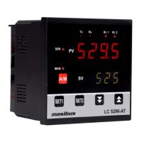
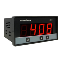
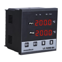
Information on the display types and key functions for different models.
Supported output types including Relay, SSR, Linear, and Motor Position Control.
Specifications for retransmission output signal, load resistance, and alarm outputs.
Details on communication interface (RS485) and power supply requirements.
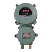
Operating and storage temperature, humidity, and other environmental factors.
Dimensions, panel cutout, weight, and mounting instructions for LC5296-AT.
Dimensions, panel cutout, weight, and mounting instructions for LC5248E-AT.
Dimensions, panel cutout, weight, and mounting instructions for LC5296V-AT.
Diagram and description of terminal connections for the LC5296-AT model.
Diagram and description of terminal connections for the LC5248E-AT model.
Diagram and description of terminal connections for the LC5296V-AT model.
Important notes and precautions for connecting wires to the controller.
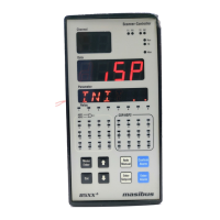
Description of keys, displays, and indicators on the LC5296-AT front panel.
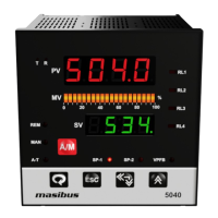
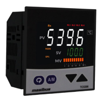
Description of keys, displays, and indicators for LC5248E-AT/LC5296V-AT.
Detailed explanation of various status indicators and control buttons on the front panel.
Graphical representation of the menu structure for LC5296-AT.
Flowchart detailing the configuration menu structure and options.
Graphical representation of the menu structure for LC5248E-AT/LC5296V-AT.
Flowchart illustrating the calibration menu and its parameters.
Description of parameters viewable and changeable during RUN mode.
Parameters for setting set points and configuring the auto-tune mode.
Detailed list of configuration parameters and their settings.
Continuation of configuration parameters and their settings.
Further configuration parameters and their settings.
Final set of configuration parameters and their settings.
Parameters related to zero, span, and retransmission calibration.
Important notes and practical examples for calibration procedures.
Explanation of the ON/OFF control mode, including hysteresis.
Details on PID control, auto-tuning process, and parameter calculation.
Explanation of Proportional Band, Integral Time, Derivative Time, and Manual Reset.
How to select control outputs and use the ramp and soak functions.
Description of motor position control without slide wire feedback.
Overview of alarm settings and a list of available alarm types.
Graphical illustrations of different alarm conditions and their behavior.
Explanation of alarm direction, delay, hysteresis, and standby modes.
Procedure for calibrating the instrument's zero and span values.
Procedure for calibrating retransmission output zero and span.
Overview of Modbus RTU communication and its application.
List of Modbus function codes used for data access.
Register addresses for process values, status, and basic settings.
Register addresses for advanced settings like alarms, PID, and communication.
Explanation of error codes and exceptional responses in Modbus communication.
Step-by-step procedure for diagnosing and resolving common operational issues.
Table showing relay and LED states for ON-OFF control logic.
Tables detailing retransmission output behavior for OPEN/OVER/UNDER conditions.
Instructions for setting jumpers for addon cards like Retransmission and Communication.
Specific jumper configurations for retransmission cards (m61Cao102, m49Acp101).
Guidelines for connecting loads and electrical safety precautions.
| Model | LC5296-AT |
|---|---|
| Type | Loop Controller |
| Protection Class | IP20 |
| Input Type | Analog |
| Input Range | Thermocouple, RTD, mA, mV, Volts |
| Output Type | Relay, Analog |
| Communication | RS485 |
| Mounting | Panel Mount |
| Control Action | PID |
| Display | Dual 4-digit LED |