Model: LC5296-AT /LC5248E-AT/LC5296V-AT masibus
Doc. Ref. no. : - m61C/om/301
Issue no. 13
User’s Manual Page 11 of 44
4. TERMINAL CONNECTIONS
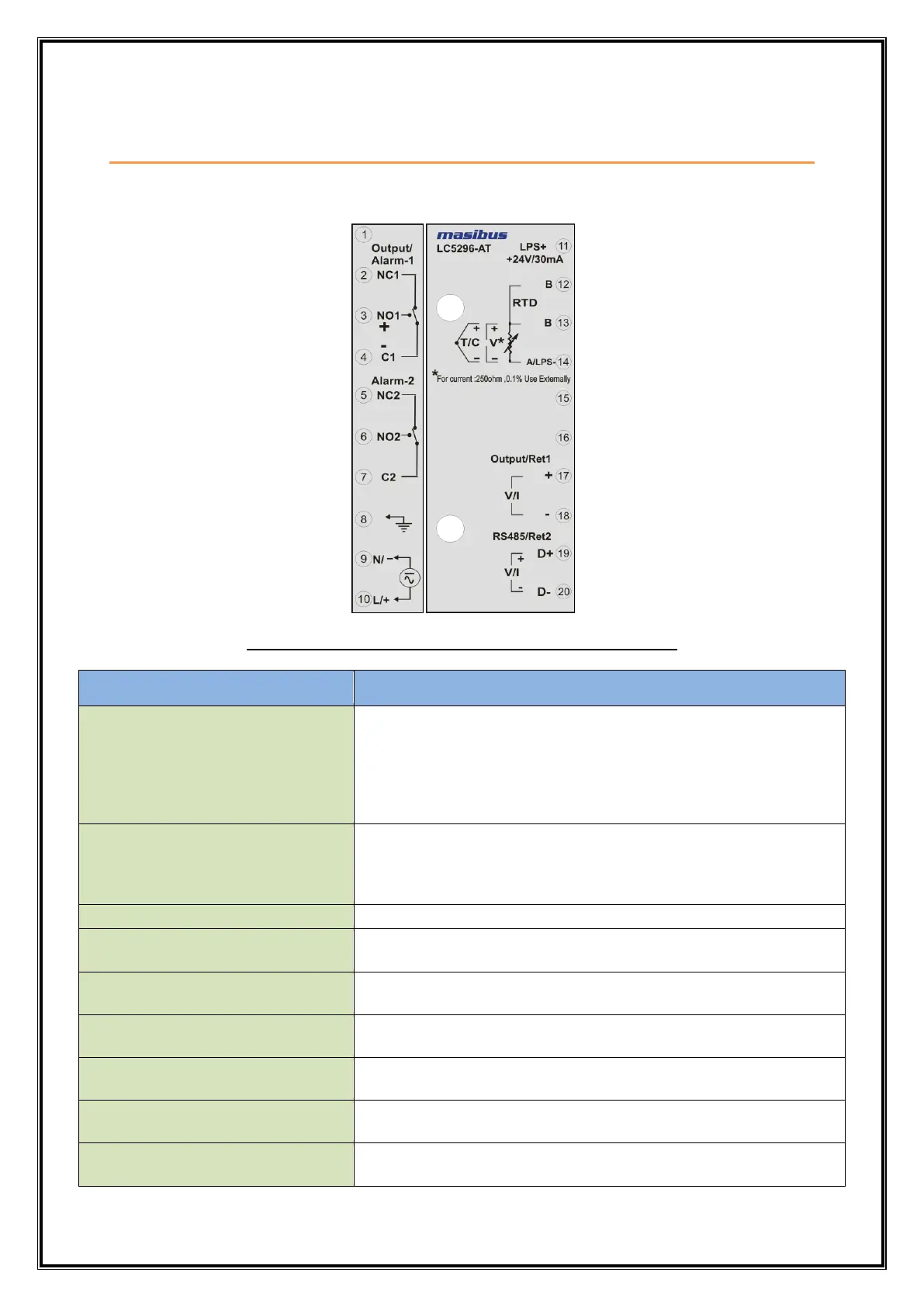
4.1 LC5296-AT
Fig 4.1: Terminal Connection Detail of LC5296-AT
For Relay-1 potential free Contacts (Use 230V -2A load)
PID/ On-Off Control o/p.
Alarm-1 o/p, if output type is Linear.
Forward Relay, if output type is Motor position control
without slide wire feedback
Terminal 3,4:- SSR Pulse o/p.
For Relay-2 potential free Contacts (Use 230V -2A load)
Alarm-2 o/p.
Reverse Relay, if output type is Motor position control
without slide wire feedback
24VDC Loop power supply
Terminal 14 is ground Reference.
For RTD Input Only
(Three wire Compensation).
13 (TC+/ V+)
14 (TC- / V- / LPS-)
For Thermocouple, RTD & Linear Input
17 (Linear Output+/RTR1+)
18 (Linear Output-/RTR1-)
For Retransmission-1 output
Linear type Control Output
19 (D+/ RTR2+)
20 (D- / RTR2-)
For Retransmission-2 output
Modbus-RTU Communication Output
 Loading...