Model: LC5296-AT /LC5248E-AT/LC5296V-AT masibus
Doc. Ref. no. : - m61C/om/301
Issue no. 13
User’s Manual Page 13 of 44
For Retransmission-1 output
Linear type Control Output
Modbus-RTU Communication Output
11 (NC2)
12 (NO2)
13 (C2)
For Relay-2 potential free Contacts (Use 230V -2A load)
On-Off Control o/p.
14 (C1)
15 (NO1)
16 (NC1)
For Relay-1 potential free Contacts (Use 230V -2A load)
PID/ On-Off Control o/p.
Alarm-1 o/p, if output type is Linear.
Terminal 3,4:- SSR Pulse o/p.
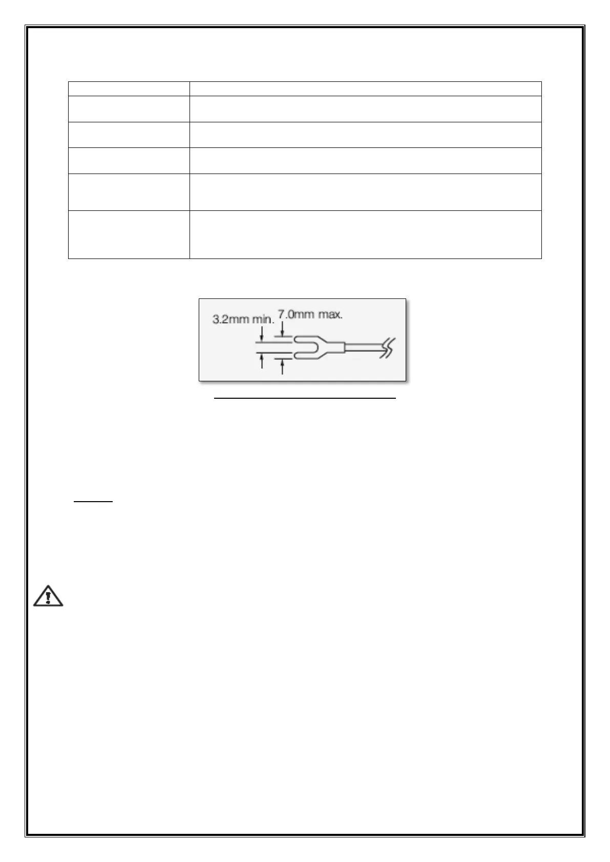
Fig 4.3:Lead Termination Detail
4.4 How to connect wires
Before carrying out wiring, turn off the power to the controller and check that the
cables to be connected are not alive because there is a possibility of electric shock.
NOTE:
All wiring must confirm to appropriate standards of good practice and local codes
and regulations. Wiring must be suitable for Voltage, Current and temperature
rating of the system.
Provide power from a single-phase instrument power supply. If there is a lot of
noise in the power line, insert an insulating transformer into the primary side of
the line and use a line filter on the secondary side. Do not place the primary and
secondary power cables close to each other.
For thermocouple input, use shielded compensating lead wires for wiring. For RTD
input, use shielded wires that have low conductor resistance and cause no
significant differences in resistance between the three wires.
Use repeater after each set of 32 instruments connected in RS-485
Communication.
Unused terminals should not be used as jumper points as they may be internally
connected, which may cause damage to the unit.
Unused control terminals should not be used as jumper points as they may be
internally connected, which may cause damage to the unit.
Use >250V-1Amp Cable for Power Supply.
Supply voltage must be below maximum voltage rating specified on the label.
 Loading...