Do you have a question about the Masibus TC 5396 and is the answer not in the manual?
Purpose and welcome to the user manual.
Manual content disclaimer, accuracy, and copyright information.
Acknowledgment of product and third-party trademarks.
Verifying all delivered items against the product list.
Details of standard accessories included with the product.
Important guidelines for safe operation and handling.
Input signal types and ranges.
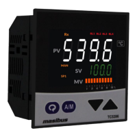
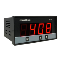
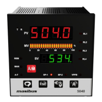
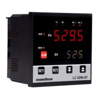
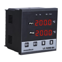
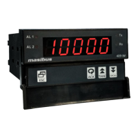
Description of the unit's display and control buttons.
Output signal types, ratings, and options.
Electrical power requirements and isolation.
Operating and storage environmental conditions.
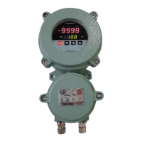
Dimensions, weight, material, and enclosure details.
Special product capabilities.
Detailed wiring procedures and notes.
Detailed breakdown of display elements and keys.
Visual representation of the controller's menu structure.
Parameters viewable and modifiable during operation.
Configuration of setpoints and alarms.
Settings for auto-tuning and PID control adjustments.
General parameter settings and adjustments.
Configuration of alarm types, hysteresis, and logic.
Configuration of control output types and limits.
Options for user-defined display parameters.
Procedures for instrument calibration.
Procedure for restoring default factory settings.
Explanation of simple on/off temperature control.
Details on proportional, integral, derivative control and auto-tuning.
Gradual setpoint changes and holding periods.
Specific mode for controlling valve or motor position.
Description of various deviation and absolute value alarms.
Steps for input zero and span adjustment.
Steps for retransmission output calibration.
Overview of Modbus RTU serial communication protocol.
Mapping of parameters to Modbus registers for data access.
Handling of communication error codes and slave status.
Guide for diagnosing and resolving common operational issues.
Logic diagrams for ON-OFF control states.
Behavior for error conditions.
Linear output behavior for error conditions.
Configuration for optional communication or output cards.
Recommendations for connecting external loads.
Safety measures for switching inductive loads.
| Brand | Masibus |
|---|---|
| Model | TC 5396 |
| Category | Controller |
| Language | English |