EasyManua.ls Logo

Masibus LC5296 DC - User Manual

Masibus LC5296 DC
30 pages
Print Icon
To Next Page IconTo Next Page
Loading...
User’s Manual
O
O
N
N
-
-
O
O
F
F
F
F
C
C
O
O
N
N
T
T
R
R
O
O
L
L
L
L
E
E
R
R
L
L
C
C
5
5
2
2
9
9
6
6
D
D
C
C
D
D
u
u
a
a
l
l
C
C
h
h
a
a
n
n
n
n
e
e
l
l
T
T
e
e
m
m
p
p
e
e
r
r
a
a
t
t
u
u
r
r
e
e
C
C
o
o
n
n
t
t
r
r
o
o
l
l
l
l
e
e
r
r
Masibus Automation & Instrumentation Pvt. Ltd.
B/30, GIDC Electronics Estate,
Sector-25, Gandhinagar-382044, Gujarat, India
+91 79 23287275-77 +91 79 23287281
Email: support@masibus.com
Web: www.masibus.com
Question and Answer IconNeed help?

Do you have a question about the Masibus LC5296 DC and is the answer not in the manual?

Summary

Introduction

Foreword

Thank you note from the manufacturer for purchasing the Dual Channel ON-OFF Temperature Controller.

Notice

Information regarding manual updates, accuracy, and copyright restrictions.

Trademarks

Lists trademarks of Masibus and other companies whose products are mentioned.

Product Ordering Code

Information on how to identify the correct product model and suffix codes from the nameplate.

List of Accessories

Details of included accessories provided with the product, to be checked for completeness.

Safety Precautions

Important safety information to prevent possible harm to users and damage to property.

Description of Signs

Explanation of warning and caution symbols used throughout the manual.

Specifications

Inputs

Technical details about analog input types, ranges, accuracy, and resolution.

Display & Keys

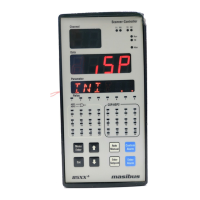
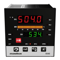
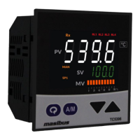
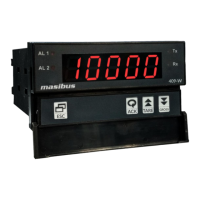
Description of the front panel display elements and key functions.

Output Types

Information on available output types such as relays and retransmission outputs.

Communication Details

Specifications for the RS485 communication interface, protocol, and baud rates.

Power Supply

Details on standard and optional power supply requirements and isolation specifications.

Environmental Conditions

Operating temperature, humidity, and storage conditions for the instrument.

Special Feature

Highlights unique functionalities like relay and retransmission mapping to input.

Physical Specifications & Mounting Details

Terminal Connections

How to connect wires?

Step-by-step guide and precautions for wiring the device correctly.

Front Panel Details

Front Panel Description

Detailed explanation of each component and indicator on the controller's front panel.

Menu Layout

Run Time Indication;Function

How to view or change parameters during the device's run time.

Set Point Setting

Procedure for configuring set point values for the controller's operation.

Configuration Mode

Detailed parameters for configuring input types, zero, span, and other settings.

Map Mode

How to map relays and retransmission outputs to specific process values.

Calibration Mode

Parameters and procedures for calibrating the instrument's inputs and outputs.

Control Function

ON;OFF Control

Explanation of the ON/OFF control logic, including hysteresis and relay operation.

Calibration Procedure

Procedure for CAL-zero and CAL-span

Steps to calibrate the zero and span for the instrument's PV inputs.

Procedure for RET-zero and RET-span

Steps to calibrate the zero and span for retransmission outputs.

Communication Protocol-MODBUS RTU

Introduction

Overview of Modbus RTU communication capabilities for the device.

Parameter Address Details

List of Modbus parameters, their absolute addresses, types, and access levels.

Exceptional Response

Codes and meanings for exceptional responses encountered during Modbus communication.

Appendix

Troubleshooting

Guide to diagnose and resolve common operational issues and problems.

On-Off Logic

Detailed explanation and table illustrating ON/OFF relay operation logic.

Retramission Output Table for Open;Over;Under Condition

Table showing retransmission output values for open, over, and under conditions.

Mapping Table for Relay and Retransmission Conditions

Table mapping relay and retransmission functions to input channels.

Jumper Settings for Add-on Card Selection & Retransmission

Instructions on configuring jumpers for selecting output types and communication cards.

Load connection

Guidance on connecting loads to the controller, including safety precautions.

Overview

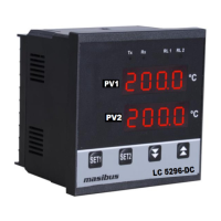
This document describes the Masibus LC5296-DC Dual Channel ON-OFF Temperature Controller, a device designed for precise temperature regulation in industrial applications.

Function Description

The LC5296-DC is an ON-OFF temperature controller that manages two independent temperature channels. Its primary function is to switch an output (relay) either ON or OFF based on whether the process temperature crosses a predefined set point. This simple control mechanism is suitable for applications where precise proportional control is not required, but rather a straightforward ON/OFF action. To prevent rapid cycling or "chattering" of the output, an ON-OFF differential, or "hysteresis," is incorporated. This ensures that the relay does not switch too frequently when the process value hovers around the set point.

The controller supports both "High type" (H-ON) and "Low type" (L-ON) set point operations. In H-ON mode, the relay turns ON when the process value reaches the set point plus the hysteresis value and remains ON until the process value drops back to the set point. Conversely, in L-ON mode, the relay turns ON when the process value drops to the set point minus the hysteresis value and stays ON until the process value rises back to the set point. Relay delays can also be configured to introduce a time delay before the relay activates after the ON condition is met.

The device also features retransmission outputs, allowing the process value to be transmitted as an analog signal (current or voltage) for external monitoring or recording. These retransmission outputs can be mapped to either input channel and are configurable for different ranges. Communication capabilities are provided via Modbus-RTU (RS485), enabling remote monitoring and configuration of parameters.

Important Technical Specifications

Inputs:

  • Input Type: Supports RTD (Pt100), Current (4-20mA, 0-20mA), and Voltage (1-5V, 0-5V, 0-10V) for both channels. Note that 0-10VDC is only possible for Channel-1.
  • Display Range:
    • Pt100 (0.1°C): -199.9 to 850.0 °C
    • Pt100 (1°C): -200 to 850 °C
    • Linear Inputs (Current/Voltage): -1999 to 9999 (Field Scalable)
  • Accuracy:
    • RTD input: ± (0.25% of Full Span + 1 degree)
    • Linear input: ± (0.1% of Full Span + 1 count)
  • ADC Resolution: 16 bits
  • Display Resolution: 0.1°C / 1 Count
  • Sampling Rate: 4 Samples/Sec
  • Sensor Open Detection: For all inputs except 0-5V.
  • RTD Excitation Current: Approximately 0.166mA.
  • Allowable RTD Wiring Resistance: Maximum 15 ohms/wire (conductor resistance between three wires should be equal).
  • Input Impedance: > 1MΩ (Voltage Input), 250Ω (Current Input).
  • Max Voltage: 20VDC.

Display & Keys:

  • PV1 & PV2 Display: 4-Digit, 7-Segment, Red, 0.56" character height. Displays process values, parameter names, and values during configuration, and error messages.
  • Status Indication: Individual RED LEDs for Relay & Communication Status (Tx, Rx, RL1, RL2).

Output Types:

  • Relay Output: 2 relays, single change-over type (C, NO, NC).
    • Rating: 2A @ 230VAC / 30VDC.
  • Retransmission Output: 1 or 2 outputs, configurable for 4-20mA, 0-20mA, 1-5VDC, 0-5VDC, or 0-10VDC.
    • Load Resistance: < 500Ω (Current o/p), > 3KΩ (Voltage o/p).
    • Output Accuracy: ±0.25% of span.
  • Loop Power Supply: 24VDC (±1V) @ 60mA with inbuilt short circuit protection.

Communication Details:

  • Interface: RS485 (2 Wire).
  • Protocol: Modbus-RTU.
  • Baud Rate: 9600, 19200, 38400 bps.

Power Supply:

  • Standard: 85-265VAC / 100-300VDC.
  • Optional: 18-36VDC.
  • Power Consumption: <10VA.
  • Data Backup: Non-volatile memory (can be written up to 100,000 times).

Environmental Conditions:

  • Ambient Temperature: 0 to 55°C.
  • Storage Temperature: 0 to 80°C.
  • Humidity: 30% to 95% RH (Non-Condensing).
  • Instrument Warm-up Time: Approx. 15 minutes.

Physical Specifications:

  • Front Bezel: 96 x 96 mm.
  • Panel Cutout: 92mm (+0.8) x 92mm (+0.8).
  • Depth Behind Panel: 65 mm with Terminal.
  • Weight: 300g Approx.
  • Enclosure Material: ABS.
  • Enclosure Protection: IP20.
  • Terminal Cable Size: 2.5 mm².

Usage Features

The LC5296-DC is designed for ease of use with a clear front panel interface.

  • Front Panel Operation: The front panel includes two 4-digit, 7-segment RED displays for PV1 and PV2, along with dedicated keys: Increment, Decrement, SET1 (Menu/Enter), and SET2 (Set Point 2 store).
  • Run Time Indication: During normal operation, the upper display shows the process value for Input-1, and the lower display shows the process value for Input-2.
  • Set Point Setting: Set points (ST-1 and ST-2) can be easily viewed and adjusted using the front panel keys. The range of set points depends on the configured sensor type.
  • Configuration Mode: A comprehensive configuration menu allows users to set various parameters such as input types, zero and span adjustments, set point types (L-ON/H-ON), decimal point positions, display brightness, serial number, baud rate, relay delays, hysteresis values, retransmission output types, and mapping. Access to this mode is protected by a password.
  • Map Mode: This mode allows mapping of relays and retransmission outputs to specific input channels (PV1 or PV2).
  • Modbus-RTU Communication: The RS485 interface enables integration into a larger control system, allowing remote monitoring and modification of all programmable parameters. This is crucial for centralized control and data logging.
  • Special Features: The device offers flexible mapping of relays and retransmission outputs to either input channel, enhancing its adaptability to different control scenarios.

Maintenance Features

  • Calibration Mode: The controller supports both CAL-zero and CAL-span calibration for PV inputs, as well as RET-zero and RET-span calibration for retransmission outputs. This allows for precise adjustments to maintain accuracy over time, compensating for sensor drift or changes in the measurement chain. Calibration can be performed digitally without opening the unit or using trim pots.
  • Troubleshooting Guide: The manual provides a detailed troubleshooting flowchart to help users diagnose common issues related to power, key operation, display, I/O signals, and communication links. This systematic approach aids in quickly identifying and resolving problems.
  • Non-Volatile Memory: All configuration parameters are stored in non-volatile memory, ensuring that settings are retained even after power loss. This memory is robust, supporting up to 100,000 write cycles.
  • Jumper Settings: The device utilizes jumpers for selecting add-on cards (retransmission or RS-485 communication) and configuring retransmission output types (voltage or current). This modularity simplifies maintenance and allows for field customization.
  • Electrical Precautions: The manual emphasizes the importance of proper wiring and the use of snubber circuits across inductive loads to prevent electrical noise, disruptions, and potential damage to the instrument, contributing to long-term reliability.
  • Isolation: The device features robust electrical isolation between primary terminals (power, relay outputs) and secondary terminals (analog I/O, communication), as well as grounding, ensuring safety and reducing interference. Withstanding voltages are specified for different isolation points.

Masibus LC5296 DC Specifications

General IconGeneral
BrandMasibus
ModelLC5296 DC
CategoryController
LanguageEnglish

Related product manuals