Do you have a question about the Masibus 409-W and is the answer not in the manual?
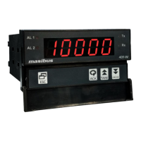
Describes the 409-W as a micro-controller based strain gauge indicator for various inputs and set points.
Advises users to check model and suffix codes to confirm the received product matches the order.
Lists the accessories provided with the product, such as mounting clamps.
Explains the function of the four keys on the front panel for operating the instrument.
Illustrates the terminal connections for power, input, output, and communication signals.
Shows the wiring diagram for connecting a Strain Gauge Input (SGI) to the 409-W indicator.
Details various configurable parameters, their display names, descriptions, and default values.
Provides a visual flow chart of the menu structure for configuring the 409-W instrument.
Presents the primary navigation path through the instrument's menu options.
Outlines the steps and options available within the instrument's calibration menu.
Defines different alarm types such as HH-high, HL-high, LL-low, and their corresponding AL1/AL2 settings.
Explains how the instrument toggles between ALARM and TRIP modes and the functionality of TRIP.
Describes the latching feature for discrete LEDs and relay status that maintains state until acknowledged.
Defines High-High alarm logic, specifying relay activation based on PV exceeding setpoints SP1 and SP2.
Defines High-Low alarm logic, specifying relay activation based on PV relative to setpoints SP1 and SP2.
Defines Low-Low alarm logic, specifying relay activation based on PV falling below setpoints SP1 and SP2.
Configures alarm behavior during an OPEN sensor condition, allowing UP Scale or DOWN Scale selection.
Details HH logic behavior during OPEN sensor conditions, affected by UP/DOWN scale settings.
Details HL logic behavior during OPEN sensor conditions, affected by UP/DOWN scale settings.
Details LL logic behavior during OPEN sensor conditions, affected by UP/DOWN scale settings.
Explains how process values are displayed under various conditions, including OPEN sensor and range limits.
Describes retransmission output behavior when the sensor is open, detailing values for different I/P types.
Parameter for setting the delay (in seconds) for relay operation after an ON condition occurs.
Explains the function of the control relay based on alarm/trip conditions and latch settings.
Outlines the steps for calibrating the instrument using front panel keys or Modbus communication.
Introduces RS-485 communication, Modbus RTU protocol, and serial number requirements for connectivity.
Lists Modbus parameters, their absolute addresses, data types, value ranges, and access types.
Details error codes and their meanings for communication queries, such as invalid function codes or addresses.
Specifies input signal ranges, accuracy, and characteristics for Strain Gauge and Digital Inputs.
Details the available retransmission output types for DC Current and DC Voltage.
Covers general operational parameters like display, keys, ambient conditions, humidity, dimensions, and weight.
Specifies power supply voltage ranges, consumption, and load excitation voltage.
Details the isolation voltage and resistance between various terminals for safety.
Outlines communication interface, speed, parity, stop bits, protocol, and error detection methods.
Lists special features like digital filter, scalability, output mapping, and key tare functionality.
Provides a flowchart to diagnose and resolve common instrument issues like inoperability or faulty operations.
Illustrates jumper locations on the AO card for selecting V or mA retransmission output types.
Advises on connecting loads, including the use of contactors for larger loads and snubber circuits.
Defines gross value and provides the formula for calculating it based on input feed, span, and zero values.
Explains tare weight as the weight of an empty object and its role in system calibration.
Describes the step value parameter's function in controlling the change of the rightmost digit in process value display.
| Communication | RS485 Modbus RTU |
|---|---|
| Mounting | Panel Mount |
| Dimensions | 96 x 96 x 110 mm |
| Protection Class | IP20 |
| Input | Thermocouple, RTD, Analog Voltage, Analog Current |
| Control Output | Relay, SSR |
| Power Supply | 85 to 265 VAC, 50/60 Hz |
| Output Current | 4-20 mA |
| Display | Dual, 4 digits, 7 segment LED display |