Do you have a question about the Masibus LC5296 and is the answer not in the manual?
Brief introduction and purpose of the user manual.
Disclaimer regarding manual content changes and accuracy.
Lists product and company trademarks and their owners.
Explains how to interpret product model and suffix codes.
Details the accessories provided with the product based on model.
Provides critical safety warnings and explains safety symbols.
Details analog input types, accuracy, resolution, and ranges.
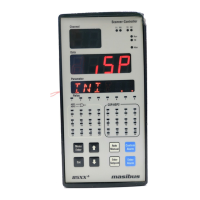
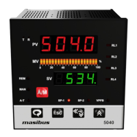
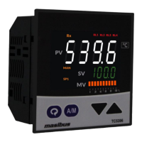
Describes front panel displays and key functions for different models.
Specifies relay and retransmission output capabilities and ratings.
Covers communication interface type and protocol.
Details power supply requirements, consumption, and isolation voltages.
Lists operating temperature, humidity, and warm-up time.
Mentions input scalability for linear input configurations.
Provides dimensions and mounting information for LC5296/5006-RN.
Provides dimensions and mounting information for LC5296-H/408-M.
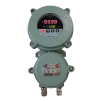
Provides dimensions and mounting information for the LC5248E model.
Details terminal assignments and functions for LC5296 and 5006-RN.
Details terminal assignments and functions for LC5296-H and 408-M.
Details terminal assignments and functions for the LC5248E model.
Provides essential guidelines for safe and correct wiring practices.
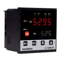
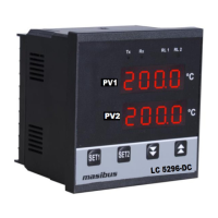
Describes front panel layout, displays, and indicators for multiple models.
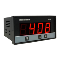
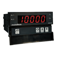
Describes the front panel layout, display, and indicators specific to the 408-M model.
Details parameters viewable or changeable during normal operation.
Explains the procedure for configuring Set Point 1 and Set Point 2.
Covers configuration parameters like Input Type, Zero, Span, and Decimal Point.
Describes the steps for performing zero and span calibration.
Details parameters viewable or changeable during run time for the 408-M.
Covers configuration parameters for the 408-M model.
Describes the calibration procedures for the 408-M model.
Explains the ON/OFF control logic, including hysteresis and relay operation.
Details the steps for calibrating the instrument's zero and span.
Explains how to calibrate retransmission outputs for zero and span.
Provides an overview of the Modbus RTU communication protocol.
Lists Modbus parameter addresses, types, and access levels.
Explains Modbus error codes and their meanings.
Provides a flowchart for diagnosing and resolving operational issues.
Details the logic states for ON/OFF control and corresponding LED indications.
Lists retransmission output values for specific input conditions.
Explains jumper configurations for selecting output types and communication cards.
Shows wiring diagrams for loads and discusses electrical precautions.
| Mounting | Panel Mount |
|---|---|
| Protection Class | IP65 |
| Input Type | Analog, Digital |
| Input Range | 4-20 mA |
| Output Type | Relay Output |
| Power Supply | 24 V DC |
| Display | LCD |
| Communication | RS485 |
| Dimensions | 96 x 96 mm |