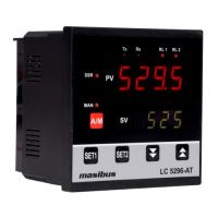
Model: LC5296-AT /LC5248E-AT/LC5296V-AT masibus
Doc. Ref. no. : - m61C/om/301
Issue no. 13
User’s Manual Page 7 of 44
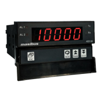
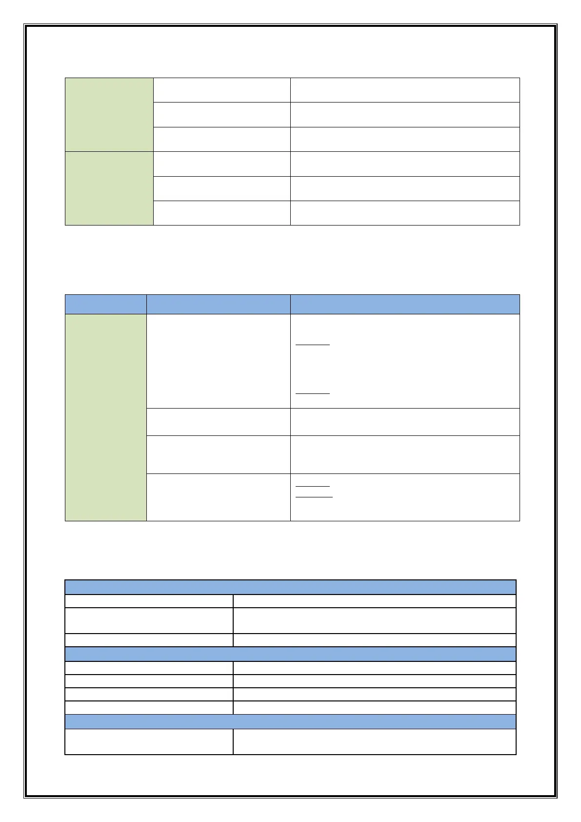
4-Digit, 7-Segment, Red, Character height of
0.40”
4-Digit, 7-Segment, Green, Character height of
0.28”
Individual RED Led’s for Relay Status,
SSR Output, Manual & Communication Status
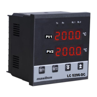
4-Digit, 7-Segment, Red, Character height of
0.36”
4-Digit, 7-Segment, Green, Character height of
0.31”
Individual RED Led’s for Relay Status,
SSR Output, Manual & Communication Status
2.3 Output Types
Output types are software selectable from the Key board or Modbus (LC5296-AT&LC5248E-
ATOnly).
LC5296-
AT/LC5248E-
AT/ LC5296V-
AT
2 Relays
Relay-1
For PID or ON-OFF Controlling.
Used as Alarm-1 Output if Output Type is
Linear
Relay-2
Alarm-2 Output
Voltage Pulse Output
Available at Terminals of Relay-1
Available at Terminals of Retransmission-1.
Linear Output Type as per selection in
Retransmission-1 Output Type.
Motor position control
without slide wire
feedback
Relay-1 As a Forward Relay
Relay-2 As a Reverse Relay
Also, Output Direction [Direct (Cooling) /Reverse (Heating)] is selectable from software.
* For LC5296-AT, LC5248E-AT, LC5296V-AT, at a time unit can support Relay or SSR
Output. (Factory settable) (Specify in Order Code)
Single Change over
Three Terminals (C, NO, NC)
Output signal On-condition
Voltage (0-5VDC, 1-5VDC, 0-10VDC) @3kΩ Min
Current (4-20mADC, 0-20mADC) @500Ω Max
 Loading...