EasyManua.ls Logo

Masibus LC5296-XP - 7.1 RUN Time Indication;Function; 7.2 Set Point Setting; 7.3 CONFIGURATION MODE

Masibus LC5296-XP
56 pages
Print Icon
To Next Page IconTo Next Page
To Previous Page IconTo Previous Page
Loading...
Model: LC5296-XP-AT/LC5296-XP/LC5296-XP-I
Doc. Ref. no.:- m61D/om/101
Issue no. 17
User’s Manual Page 34 of 56
7.1 RUN Time Indication/Function
Following parameters can view or change during run time.
For Thermocouple input type, Press Increment key to show ambient
temperature.
7.2 Set Point Setting
Pressing SET key PV Display shows C1.sp (C1.SP) message. SV display shows
ControlSet Point-1 Value. Use Inc and Dec key to modify value. OR press MENU
key again to set value for ControlSet Point-2 Value.
7.3 CONFIGURATION MODE
Set Point Setting:
Parameter
(PV display)
Setting name and
description
Default
value
Shows only
if
Symbol
Name
C1.SP
(C1.sp)
Control Set Point 1
Range Depending on PV
sensor type selected
100
-
C2.SP
(C2.sp)
Control Set Point 2
Range Depending on PV
sensor type selected
100
-
CONFIGURATION PARAMETERS
Parameter
(PV display)
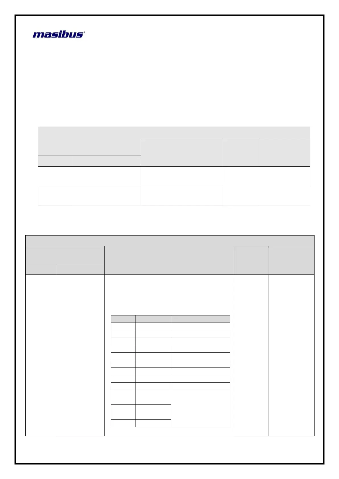
Setting Name & Description
Default
Value
Show if Only
Symbol
Name
INPT
(inpt)
INPUT Type
Set PV Input Type
tC e / tC j / tC K / tC t / tC b /
tC r / tC s / rtd.1 / rtd/ 0-5v / 1-
5v/0-10
Value
Input Type
Range
0
TC E
-200 to 1000 °C
1
TC J
-200 to 1200 °C
2
TC K
-200 to 1372 °C
3
TC T
-100 to 400 °C
4
TC B
450 to 1800 °C
5
TC R
0 to 1768 °C
6
TC S
0 to 1768 °C
7
RTD.1
-199.9 to 850.0 °C
8
RTD
-200 to 850 °C
9
0-5 V /
0-20 mA*
-1999 to 1999
10
1-5 V / 4-
20 mA*
11
0-10V
*Use external 250ohms,0.1% for
TC K

Related product manuals