Do you have a question about the Masibus 8208 and is the answer not in the manual?
Opening remarks and thank you for purchasing the 8208 scanner.
Manual content changes, accuracy, and copyright information.
Lists product and company trademarks mentioned in the manual.
Indicates the revision history and publication date of the manual.
Verify all items are present and undamaged after unpacking.
Identify specific model and suffix codes of the scanner.
Details accessories provided with the scanner based on model and suffix codes.
Panel mounting requirements and optimal environmental conditions for installation.
Physical dimensions of the unit and panel cutout specifications.
Guides on proper wiring practices, safety precautions, and connection details.
Details supported input types, their ranges, and accuracy specifications.
Covers input impedance, noise rejection, outputs, communication, and power supply.
Outlines power consumption, insulation, construction, and environmental operating conditions.
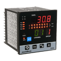
Describes the components and indicators on the front panel of the scanner.
Illustrates the terminal layout and connection details on the back plate.
Provides dimensions and specifications for recommended terminal lugs.
Used to enter sub-menus and save parameters for configuration.
Used to exit sub-menus and return to the run mode.
Increments parameter values or digits during setting.
Shifts digits for setting or acknowledges alarms/trips.
Switches between automatic and manual operating modes.
Describes viewing and changing parameters during normal operation.
Details access to parameter levels, calibration, and factory reset.
Presents tables for input type selection and other configurations.
Explains settings for logic, function, delay, open sensor, mapping, and types.
Details relay/OC logic and basic functional behavior with tables.
Adjusts ambient temperature compensation for thermocouple inputs.
Calibrates the PV sensor input for zero and span.
Calibrates voltage or current retransmission output signals.
Lists calibration requirements for different input groups.
Covers Modbus function codes, exception responses, and protocol details.
Details Modbus addresses and parameters for holding registers.
Lists Modbus addresses for reading output status registers.
Tables for input type selection and various relay group/selection settings.
Covers relay type, latch, baud rate, parity, and retransmission settings.
Shows PV input status messages during burnout conditions for different input types.
Details retransmission output behavior for open, over, and under conditions.
Covers OC card terminals, Modbus addresses, and relay/OC configuration options.
| Number of Channels | 8 |
|---|---|
| Power Supply | 24 VDC |
| Type | Scanner |
| Communication | RS485 |
| Accuracy | ±0.1% FS |
| Operating Temperature | 0°C to 50°C |
| Dimensions | 96mm x 96mm |
| Operating Humidity | 10% to 90% RH (non-condensing) |