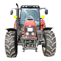
Massey Ferguson 6400 - Issue 1
02C01.15
Splitting - GBA20 gearbox / Centre housing
On the gearbox
75. Check the presence and correct positioning of the
PTO shaft.
76. Check:
Version with no creeper unit
- Presence of the union shaft (1) composed of the
sleeves (2) and double pins (3) (Fig. 18).
Version with creeper unit.
- Correct assembly of shaft (1) composed of
sleeve (2) and double pin (3) (Fig. 19).
- Correct operation of the control mechanism (fork
and coupler) in each position.
77. Push the fork (4) towards the front of the gearbox
in direct drive position (Fig. 19).
Remark
The gearbox output shaft supports the shaft (1) via the
needle roller bearing (5) (Fig. 19).
On the centre housing
Remark
The rotation of the control finger “D” of the creeper
gears is limited by the presence of the studs and nuts
assembly (1) in the centre housing (tractors with
closed centre hydraulics - Fig. 20).
78. Pull the pin (2) outwards (Fig. 12) and direct the
“D” finger towards the front of the centre housing
(Fig. 20).
79. Couple the gearbox to the centre housing.
Reminder
If there is resistance when moving the elements
(gearbox, centre housing) together, do not force them,
and find the cause of the problem.
80. When the elements are joined, remove the guide
studs. Insert the screws (1) according to the mark-
ings made at disassembly (Fig. 14) and tighten to a
torque of 155 to 195 Nm.
Fig. 18
Fig. 19

 Loading...


