3 9 9 9
11
12
13
10
7
4
2
3
5
6
9
8
1
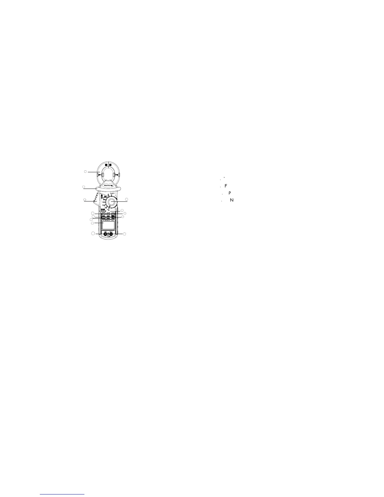
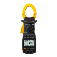
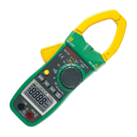
Fig.1 MS2010B Front arrangement
- 5 -
2-1 Panel description
1. Clamp jaw ; it is as current transformer(CT) when measuring
current flowing through the conductor .
2. Trigger
3. Clamp Barrier:
4. LCD display
5.‘H/ * ’ button : Hold & Back Light
When push this button, the display will keep the last reading.
Once push again, the
Meter will return the normal mode.
6. Knob: it is rotary switch for select function.
7. ‘Hz/%’button: Frequency & Duty cycle mode
8
.
‘RANGE’ button: Change Auto or Manual mode
9
.
‘FUNC’ button : Change function mode
10
.
‘LPF’ button: Used as Low Pass Filter ON/OFF switch.
11
.
‘INPUT’ terminal
12. ‘COM’ terminal
13. ‘REL’ push button: Relative measurement mode
- 6 -
2-2. LCD display