Input terminal for measuring the first
phase; use yellow test probe for
connection.
Input terminal for measuring the 2nd
phase; use black test probe for connection.
Common terminal: ground input terminal
(earthing) for all measuring functions; use
black test probe for connection.
FunctionTerminal
V1
COM/V2
V3
Input terminal for measuring the 3rd
phase; use green test probe for
connection.
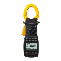
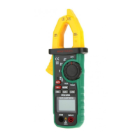
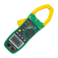
05 06
1. Current clamp size: Φ 50 mm
2. HOLD button :DATA HOLD button; press down
HOLD button, and the last reading will be held and
displayed on the display, and “HOLD” symbol will be
shown; press HOLD button again, and the meter will
switch back to normal measurement mode.
3. Function-switching knob :Rotation knob for selecting
different measuring function
4. Function-selection button: Button for operating the
measuring functions
5. Input terminal
6. LCD display :4-digit digital display; 7-section LCD
for displaying measurement operation function, test
result, and unit sign.
7. Trigger :Press down the trigger, and the clamp will
open; release it, and the clamp will close.
8. RS232C interface: Dedicated optical-electrical
interface wire is used for online communication with
PC, as well as for recording data and data trend curve
in PC.
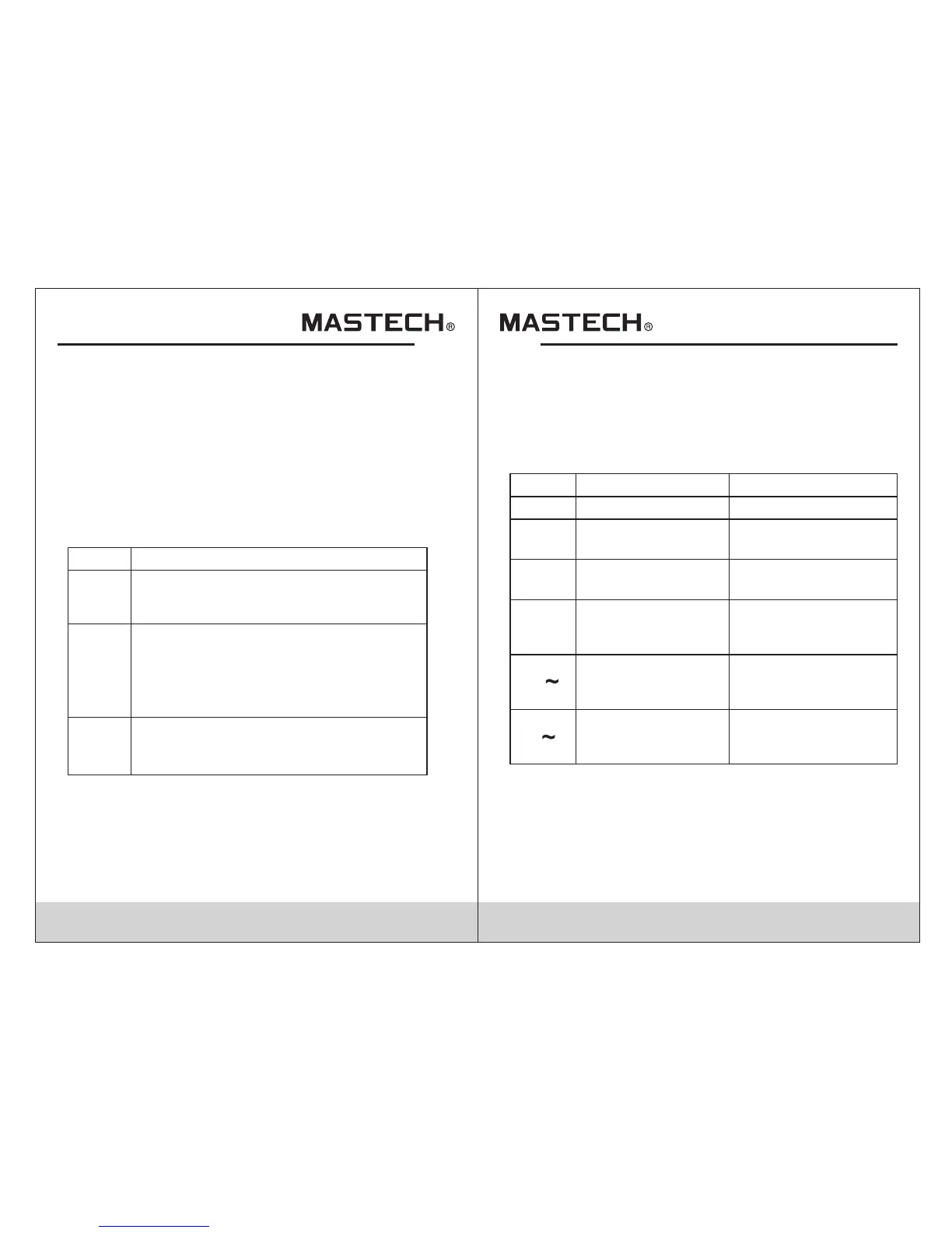
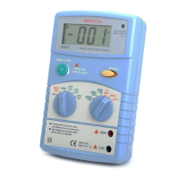
Knob Switch Operations
The function-switching knob is used for powering-on and
for switching to any measurement function in the
following table.
For measuring
active power, etc.
For measuring phase
angle, such as cos Φ
and sin Φ, etc.
For powering-offPowering-off position
Sign
Knob position
Functions
OFF
Active power position
(1 phase)
Single-phase/phase-
angle Test position
For measuring 3-
phase apparent power,
etc.
For measuring
AC-current
harmonics, etc.
For measuring
AC-Voltage
harmonics, etc.
AC-voltage
harmonics test
position
AC-Current
harmonics test
position
3-phase apparent
power position
KW/Φ
(3 phase)
A
KW
Φ
(1 phase)
V
Note:
When the meter is automatically powered off, be sure to
switch the knob to “OFF” position; turn on the meter after
5 seconds.