32
33
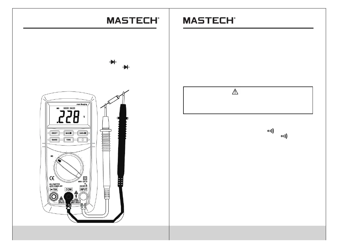
4.18 Testing Diode
4.18.1 Connect the black test lead to the COM jack and
the red test lead to the INPUT jack. (The polarity
of red lead is '+')
4.18.2 Set the transform switch at the range position.
4.18.3 put down the 'FUNC.' transformed at test.
4.18.4 Connect the red lead to the anode, the black
lead to the cathode of the diode under testing.
4.18.5 You can get reading from LCD.
4.19 Continuity Test
When testing the circuit continuity, be sure that
the power of the circuit has been shut down and
all capacitors have been discharged fully.
WARNING
4.19.1 Connect the black test lead to the COM jack and
the red test lead to the INPUT jack.
4.19.2 Set the transform switch at the range position.
4.19.3 put down the 'FUNC.' transformed at continuity
test.
4.19.4 Connect test leads across two points of the circuit
under testing.
4.19.5 If continuity exists (i.e., resistance less than
about 50 ), built-in buzzer will sound.Ω
Note:
• If the input open circuit (or the circuit resistance
measured is higher than 200 ), then the figure‘0L’
will be displayed.
Ω
Note:
• The meter will show the approximate forward voltage
drop of the diode.
If the lead connection is reversed, only figure 'OL' will
be displayed.
When the input is not connected, i.e. at open circuit,
the figure 'OL' will be displayed.
•
•