1110
Continuity Measurement:
Rotate function selection switch to continuity
measurement position, and turn off the power to
the circuit to be tested
Connect black and red test probe to COM input
jack and respectively.
Measure the circuit to be tested with other ends
of test probes.
If the measured circuit resistance is less than
about 40Ω, the buzzer will sound continuously.
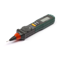
Non-Contact Voltage (NCV)
Hold down the “NCV” key and move the tip of the clamp
toward the conductor under test. If the detected voltage
is ≥ 110V AC (rms), the NCV indicator will flash and the
buzzer will beep.
Note
1)Do not rely solely on NCV detection to determine
the presence of voltage. Detection can be affected
by socket design, insulation thickness, or other factors.
2)lnterference from outside sources could accidentally
trigger the NCV detector.
1
2
3
4
When measuring resistance or circuit continuity,
to avoid injury or meter damage, turn off the
power to the circuit to be measured and
discharge all capacitors.
General Specifications
Operating environment and condition: 600V CAT lIl,
pollution grade: lI.
Elevation < 2000 m
Environment temperature and humidity: 0~40°C,
<80% RH (do not use meter when temperature <10°C).
Storage temperature and humidity: -10~60°C,
<70% RH (remove the battery).
Temperature coefficient: 0.1xAccuracy/°C
(<18°C or >28°C).
The maximum allowable voltage between
measurement end and ground: 600V DC or 600V
AC RMS.
Sampling rate: about 3 times/s.
Display: 3 5/6 bits of digit LCD display.
Over-range indication: LCD will show “OL”.
Low battery indication: When the battery voltage
is lower than the normal operating voltage, “ ”
will display on the LCD display.
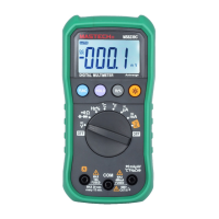
Frequency/Duty Cycle
Insert the red test lead in the “INPUT” jack and the
black lead in the “COM” jack.
Move the rotary switch to the “Hz%” position.
Connect the test leads across the circuit to be
measured.
Read measured frequency on the display.
Read measured duty cycle on the display.
1
2
3
4