3.2.7
3.2.7
3.2.7
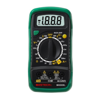
3.2.7 Transistor
Transistor
Transistor
Transistor measurement
measurement
measurement
measurement
To
To
To
To avoid
avoid
avoid
avoid electrical
electrical
electrical
electrical shock
shock
shock
shock and/or
and/or
and/or
and/or damage
damage
damage
damage to
to
to
to the
the
the
the
instrument,
instrument,
instrument,
instrument, before
before
before
before attempting
attempting
attempting
attempting to
to
to
to insert
insert
insert
insert
transistors
transistors
transistors
transistors for
for
for
for testing,
testing,
testing,
testing, always
always
always
always be
be
be
be sure
sure
sure
sure that
that
that
that test
test
test
test
leads
leads
leads
leads have
have
have
have been
been
been
been disconnected
disconnected
disconnected
disconnected from
from
from
from any
any
any
any
measurement
measurement
measurement
measurement circuits
circuits
circuits
circuits
.
1. Set the rotary switch to hFE
hFE
hFE
hFE range.
2. Determine whether the transistor to be tested is NPN or
PNP type and locate the Emitter, Base and Collector leads.
3. Insert leads of the transistor into proper holes of the hFE
socket.
4. The meter will show the approx. hFE value at test condition
of base current 10 μ A and Vce 2.8V.
3.2.8
3.2.8
3.2.8
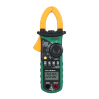
3.2.8 Current
Current
Current
Current measurement
measurement
measurement
measurement (with
(with
(with
(with clamp,
clamp,
clamp,
clamp, optional)
optional)
optional)
optional)
To
To
To
To avoid
avoid
avoid
avoid electrical
electrical
electrical
electrical shock
shock
shock
shock and/or
and/or
and/or
and/or damage
damage
damage
damage to
to
to
to the
the
the
the
instrument,
instrument,
instrument,
instrument, do
do
do
do not
not
not
not apply
apply
apply
apply more
more
more
more than
than
than
than 250Vdc
250Vdc
250Vdc
250Vdc or
or
or
or
250Vac
250Vac
250Vac
250Vac rms
rms
rms
rms between
between
between
between the
the
the
the terminal
terminal
terminal
terminal and
and
and
and the
the
the
the
COM
COM
COM
COM terminal.
terminal.
terminal.
terminal.
1. Set the rotary switch to the range.
2. Press /~
/~
/~
/~ key to select DCA or ACA measuring mode.
3. Connect the leads of the clamp to the COM
COM
COM
COM and
terminals of the meter.
4. Read the displayed value. The polarity of the V Ω terminal
connection will be indicated when making a DCA
measurement.
5. When only the figure “ OL " displayed, it indicates overrange
situation.
19
3.2.9
3.2.9
3.2.9
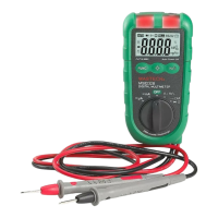
3.2.9 Current
Current
Current
Current measurement
measurement
measurement
measurement
To
To
To
To avoid
avoid
avoid
avoid damage
damage
damage
damage to
to
to
to the
the
the
the Meter
Meter
Meter
Meter or
or
or
or injury
injury
injury
injury if
if
if
if the
the
the
the
fuse
fuse
fuse
fuse blows,
blows,
blows,
blows, never
never
never
never attempt
attempt
attempt
attempt an
an
an
an in-circuit
in-circuit
in-circuit
in-circuit current
current
current
current
measurement
measurement
measurement
measurement where
where
where
where the
the
the
the open-circuit
open-circuit
open-circuit
open-circuit potential
potential
potential
potential
to
to
to
to earth
earth
earth
earth is
is
is
is greater
greater
greater
greater than
than
than
than 250V.
250V.
250V.
250V.
To
To
To
To avoid
avoid
avoid
avoid damage
damage
damage
damage to
to
to
to the
the
the
the meter,
meter,
meter,
meter, check
check
check
check the
the
the
the meter's
meter's
meter's
meter's
fuse
fuse
fuse
fuse before
before
before
before proceeding.
proceeding.
proceeding.
proceeding. Use
Use
Use
Use the
the
the
the proper
proper
proper
proper
terminals,
terminals,
terminals,
terminals, function,
function,
function,
function, and
and
and
and range
range
range
range for
for
for
for your
your
your
your
measurement.
measurement.
measurement.
measurement. Never
Never
Never
Never place
place
place
place the
the
the
the probes
probes
probes
probes in
in
in
in parallel
parallel
parallel
parallel
with
with
with
with a
a
a
a circuit
circuit
circuit
circuit or
or
or
or component
component
component
component when
when
when
when the
the
the
the leads
leads
leads
leads are
are
are
are
plugged
plugged
plugged
plugged into
into
into
into the
the
the
the current
current
current
current terminals.
terminals.
terminals.
terminals.
The Meter's current ranges are 400.0 µ A, 4000 µ A, 40.00mA,
400.0mA, and 10.00A.
To
measure current:
1. Turn off power to the circuit. Discharge all high voltage
capacitors.
2. Set the rotary switch to the µ A, mA or
A
range.
3. Press /
/
/
/ ~
~
~
~ key to select DCA or ACA measuring mode.
4. Connect the black test lead to the COM terminal and the
red test leads to the mA terminal for a maximum of
400mA. For a maximum of 10A, move the red test lead
to the A terminal.
5. Break the circuit path to be tested.
Touch the black probe to the more negative side of the
break; touch the red probe to the more positive side of
the break. (Reversing the leads will give a negative
reading, but will not damage the Meter.)
6. Turn on power to the circuit; then read the display. Be
sure to note the measurement units at the right side of
the display ( µ A, mA or A). When only the figure "OL"
displayed, it indicates overrange situation and the
higher range has to be selected.
20