11
ASSEMBLY INSTRUCTIONS
10
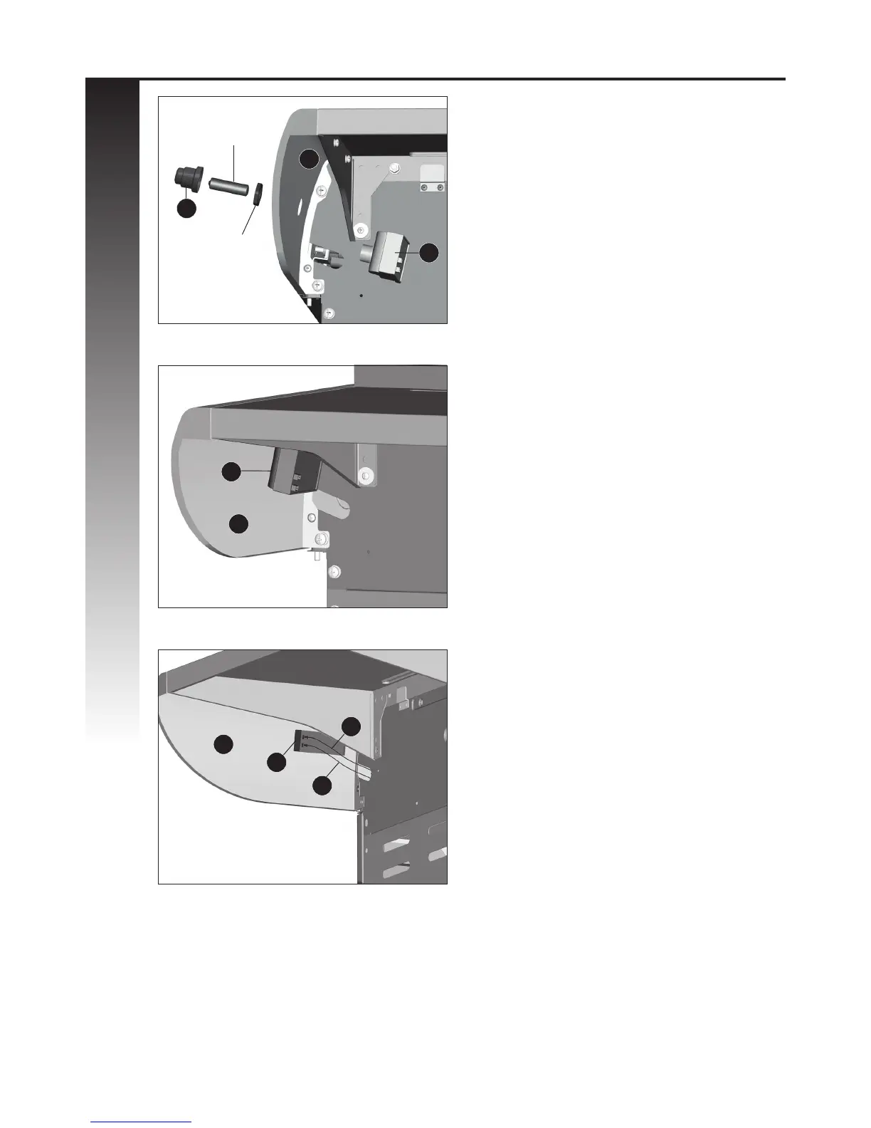
ELECTRONIC IGNITION ASSEMBLY
a. Remove the Ignition Battery Cover (CF2) and
the plastic nut from the Electronic Ignition
Assembly (CF1).
b. Position the Electronic Ignition Assembly (CF1)
through the opening in the Right Side Shelf
Fascia (DK) and secure using the plastic nut.
c. Insert one “AA” battery into the battery
compartment (CF1) with the positive end
facing outward, as shown. Secure using the
Ignition Button (CF2).
* Battery not included.
d. Insert the Electrode Set, Main Burner Wire (CG)
and the Side Burner Electronic Wire (DH) into
the Electronic Ignition Assembly (CF1)
as shown. Ensure that the wires are pushed
in rmly.
Note: Both wire connectors are the same.
A
B
C
Underneath right side shelf
Underneath right side shelf
Underneath right side shelf
DK
CG
DK
Battery
Plastic Nut
CF1
CF1
CF1
DH
DK
CF2
+
-