EasyManua.ls Logo

Master Chef E500 User Manual

Master Chef E500
25 pages
To Next Page IconTo Next Page
Page #1 background imageLoading...
Page #1 background image
E500 Barbecue
Assembly Manual
85-3044-6 (G45311) Propane
85-3045-4 (G45312) Natural Gas
1 YEAR LIMITED WARRANTY
Manual Revision #: 12022013 PD
TM
MC
ANS Z21.58b-2012-CSA 1.6b-2012
READ AND SAVE MANUAL FOR FUTURE REFERENCE.
Assemble your grill immediately.
Missing or damaged parts claims must be submitted within 30 days of purchase date.
For product inquiries, parts, warranty and troubleshooting support,
please call 1-855-453-2150.
Question and Answer IconNeed help?

Do you have a question about the Master Chef E500 and is the answer not in the manual?

Master Chef E500 Specifications

General IconGeneral
BrandMaster Chef
ModelE500
CategoryGrill
LanguageEnglish

Summary

Master Chef E500 Barbecue Assembly Manual

Safety Warnings and Precautions

General Safety Instructions

Read and follow all safety statements, assembly instructions, use and care directions.

Hazard Alerts and Handling

Information on dangers like gas leaks, sharp edges, and hot surfaces.

Hardware and Tools for Assembly

Hardware Pack Details

Detailed list of screws, nuts, washers, and other hardware components.

Tools Required for Assembly

List of necessary tools like screwdrivers and wrenches.

Propane Model Parts List

Propane Model Exploded Diagram

Natural Gas Model Parts List

Natural Gas Model Exploded Diagram

Assembly Instructions: Basic Assembly

Step 1: Castor Assembly

Attaching castors (locking and regular) to the bottom shelf.

Step 2: Side Panel Attachment

Assembling side panels to the bottom shelf.

Assembly Instructions: Main Structure

Step 3: Lid and Burner Box Assembly

Positioning the top lid and burner box onto the cart assembly.

Step 4: Upper Back Panel Installation

Attaching the upper back panel to the side panels.

Assembly Instructions: Side Shelves

Step 5: Door Support Rail Attachment

Assembling the door support rail to the upper side panels.

Assembly Instructions: Left Side Shelf

Step 6: Match Holder Installation

Attaching the match holder to the side panel of the burner box.

Step 7: Infrared Components

Assembling grease tray rails and infrared burner lid.

Assembly Instructions: Left Side Shelf Detail

Step 8: Left Side Shelf Assembly

Mounting and assembling the left side burner shelf.

Assembly Instructions: Side Burner Valve

Step 9: Side Burner Valve and Knob

Installing the side burner valve stem and control knob.

Assembly Instructions: Infrared Side Burner

Step 10: Infrared Burner Setup

Positioning electrode spacer and burner, aligning brackets.

Assembly Instructions: Side Burner Grate

Step 10 (Cont.): Venturi Clip and Grates

Connecting burner with clip, positioning grate and grease tray.

Assembly Instructions: Right Side Shelf

Step 11: Right Side Shelf Assembly

Mounting and assembling the right side burner shelf.

Assembly Instructions: Electronic Ignition

Step 12: Electronic Ignition Setup

Installing igniter assembly, battery, and electrode sets.

Assembly Instructions: Rotisserie and Heat Shield

Step 13: Rotisserie Valve and Knob

Assembling rotisserie burner valve and control knob.

Step 14: Heat Shield Installation

Attaching heat shield to door support rail and back panel.

Assembly Instructions: Grease Tray

Step 15: Grease Tray Tracks

Assembling left and right tracks for the grease tray.

Assembly Instructions: Doors

Step 15 (Cont.): Grease Tray Insertion

Inserting the grease tray into the upper back panel.

Step 16: Door Handle Attachment

Assembling door handles to the left and right door assemblies.

Assembly Instructions: Door Installation

Step 17: Door Assembly

Assembling right and left door assemblies to the unit.

Assembly Instructions: Burner Components

Step 18: Flame Tamers

Positioning flame tamer support braces and flame tamers.

Assembly Instructions: Grates and Warming Rack

Step 19: Cooking Grate Placement

Placing the cooking grates into the burner box.

Step 20: Warming Rack Installation

Inserting warming rack positioning rods into the burner box.

Assembly Instructions: Fuel Connection

Step 21: Propane Tank Connection

Connecting propane tank and regulator to the barbecue.

Step 22: Natural Gas Hose Connection

Connecting natural gas hose to the side burner valve.
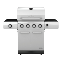
Related product manuals