9
ASSEMBLY INSTRUCTIONS
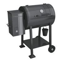
Left side view
7
7
6
6
YOU WILL NEED:
YOU WILL NEED:
15
11
X 1
X 4
9
12 13 14
X 1
X 4 X 4 X 4
EB
EA
BA
Attach the Match Holder (BI) to the left side panel
of the Burner Box Assembly.
BI
6
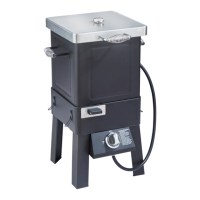
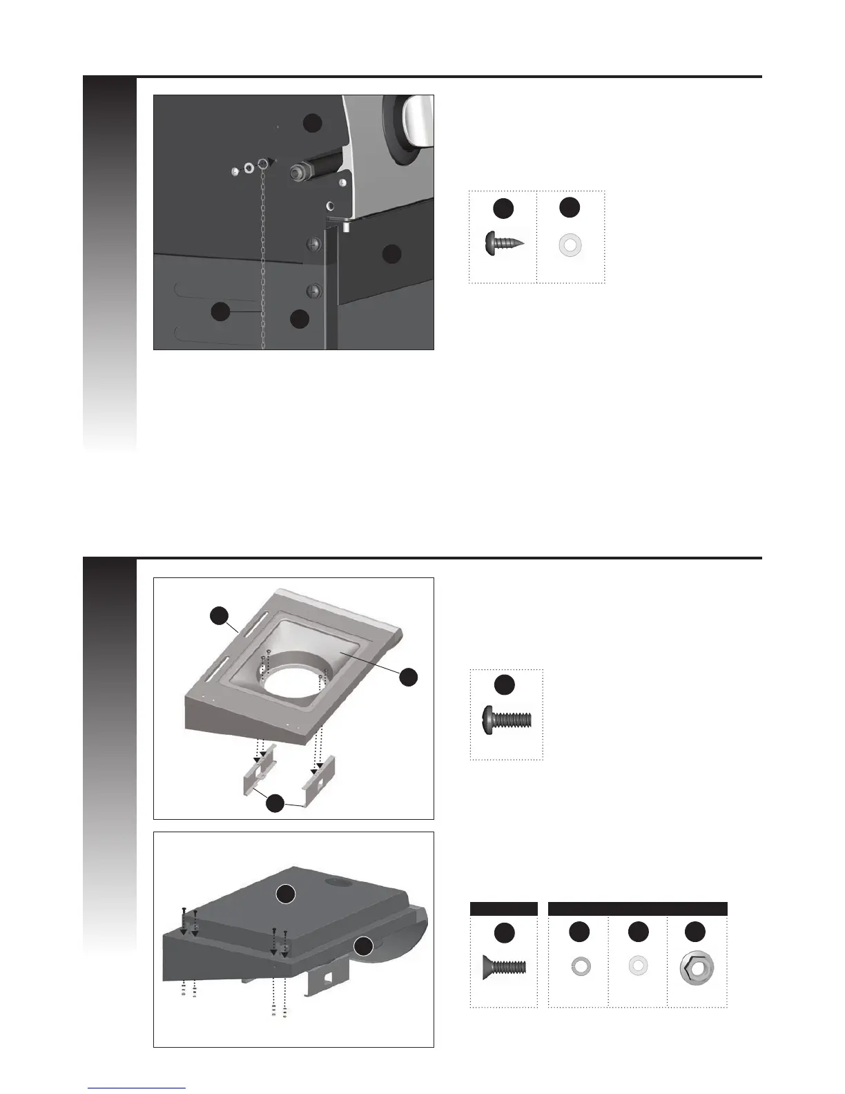
b. Attach the infrared burner lid (DF1) to the left
side burner shelf table (DA).
a. Assemble infrared grease tray rails (DJ) to the
infrared support frame (DC) located on the left
sear stove side shelf (DA) as shown in gure A.
7
DA
DF1
A
B
B2
B2
A1
A1
A1 B2
DC
DJ
DA
YOU WILL NEED:
7
X 4