15
ASSEMBLY INSTRUCTIONS
12
View, under right side shelf
View, under right side shelf
View, under right side shelf
View, under right side shelf
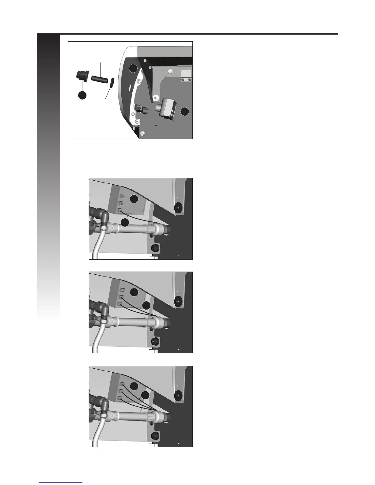
ELECTRONIC IGNITION ASSEMBLY
a. Remove the electronic ignition button (CH2)
and the plastic nut from the Electronic Igniter
Assembly (CH1)
b. Position the Electronic Igniter Assembly (CH1)
through the opening in the Right Side Shelf
Fascia (DI) and secure using the plastic nut.
c. Insert one “AA” battery into the battery
compartment (CH1) with the positive end
facing outward, as shown. Secure using the
electronic ignition button (CH2).
* Battery not included.
Note: All wire connectors are the same.
d. Insert the Electrode Sets, for the Main Burner
(CI), the infrared side burner (DE), and the
rotisserie burner (BM), into the Electronic
Igniter Assembly (CH1). (Figure B, C and D)
Ensure that the wire is pushed in rmly.
DI
CH1
CH1
CH1
Battery
CH1
CI
DE
BM
CH2
A
B
C
D
Plastic Nut
+
-