12
ASSEMBLY INSTRUCTIONS
10
DC
DB
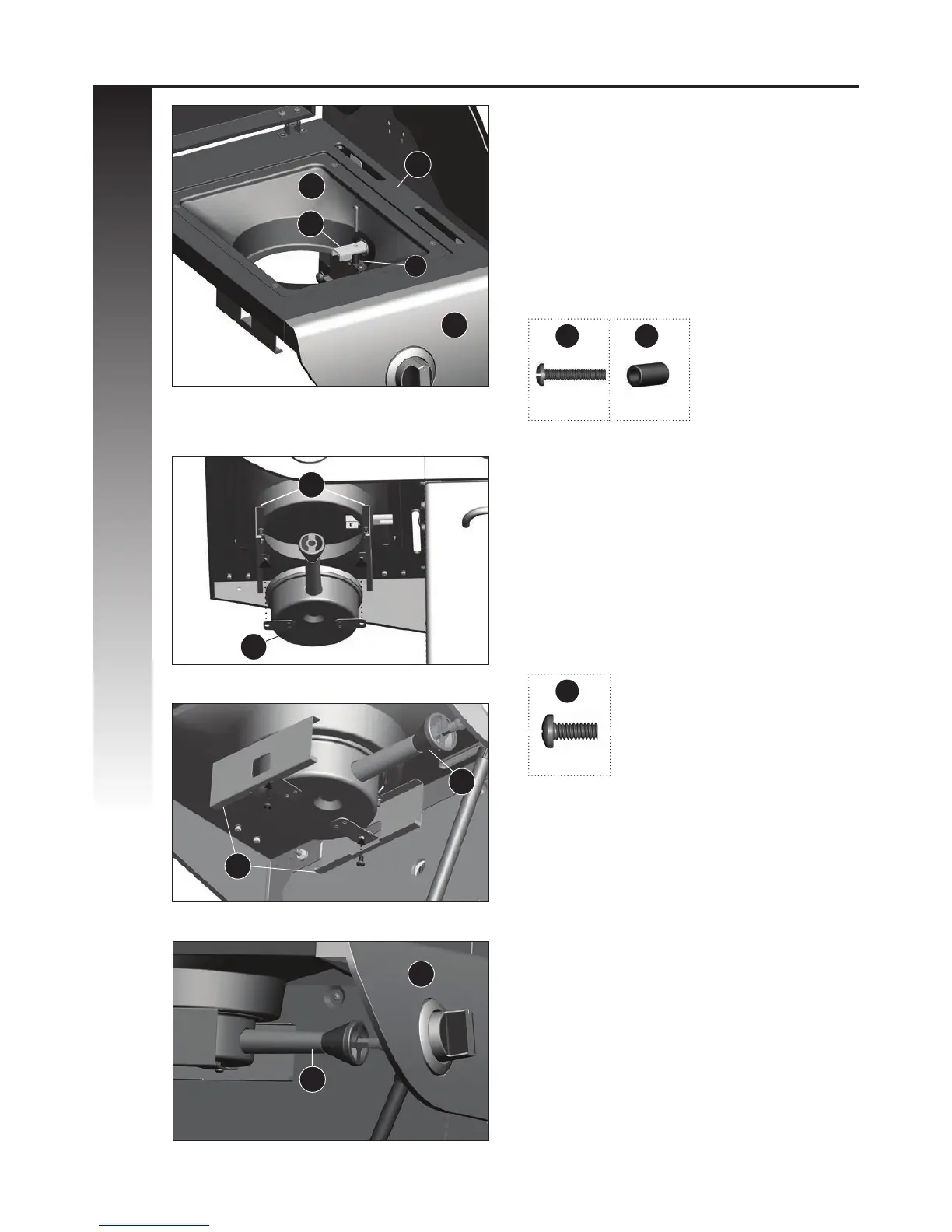
a. Position the electrode spacer (#19) on the
infrared support frame (DC) and then feed
the infrared burner electrode (DE) through
the opening on the right side of the infrared
support frame (DC). Assemble using hardware
as shown in gure A.
NOTE: the infrared electrode (DE) set can be
found attached to the infrared side burner valve
(CC).
YOU WILL NEED:
10 19
X 1 X 1
A
B
C
b. To complete assembly of the infrared side
burner (DD), align the brackets of the infrared
side burner (DD) to the brackets located on the
infrared grease tray rails (DJ) as shown in gure
B and C. Assemble using hardware.
IMPORTANT: Make sure that the infrared side
burner (DD) engages the sear stove burner
valve (CC) before tightening hardware
(gure D).
YOU WILL NEED:
7
X 2
DD
DJ
DD
View from underneath left side shelf
D
View from underneath left side shelf
View from above, left side shelf
View from underneath left side shelf
19
DA
DE
DJ
DD
DB