10
8
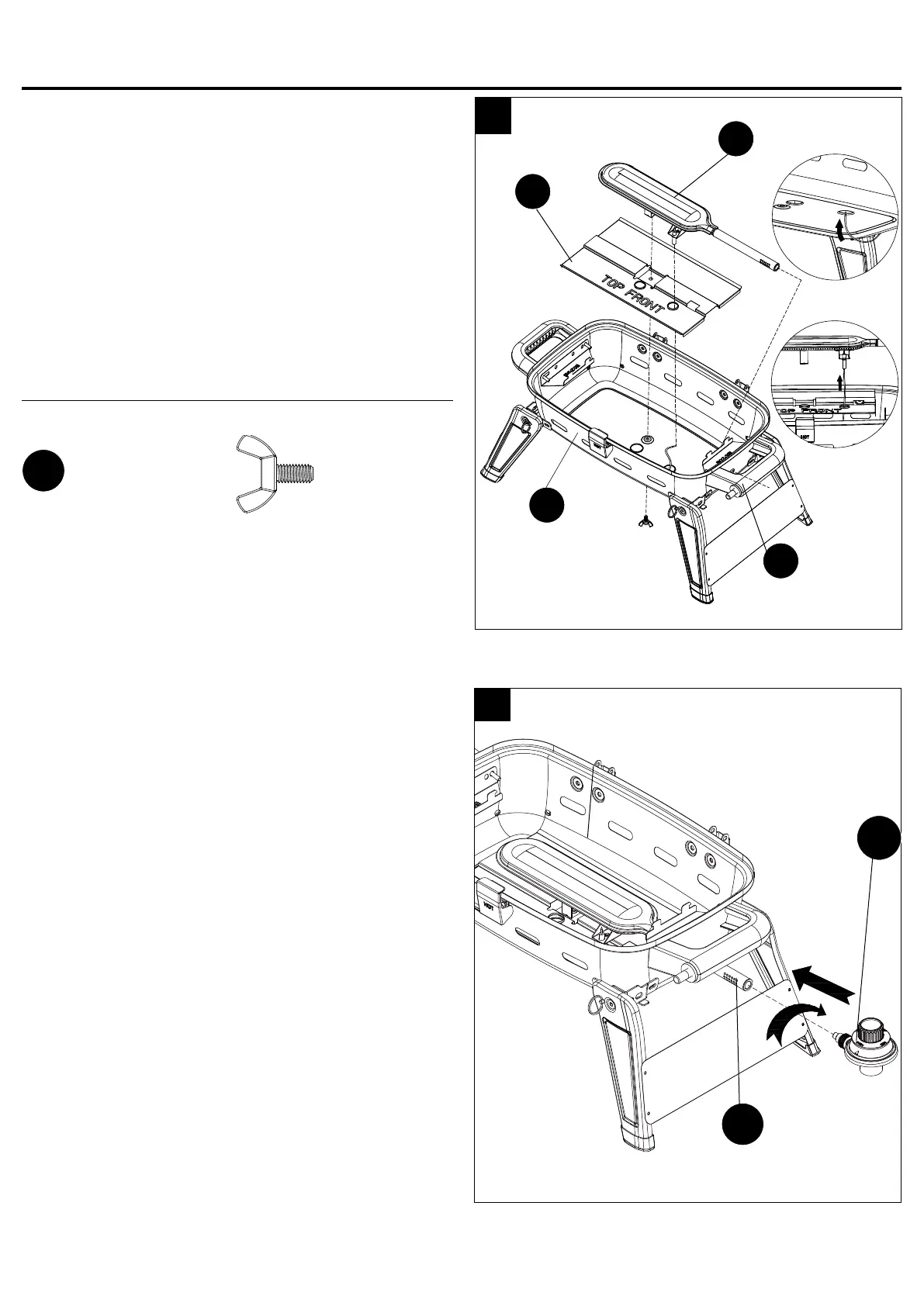
Step 7: Attach Heat Shield, Burner and Igniter Wire
Align the holes in the burner (G), heat shield (H)
and bottom bowl (K). Then insert the M6x12 wing
bolt (CC) into the holes shown in Fig.7. Tighten the
screw complelely.
Plug the igniter wire on the right handle assembly (L)
to the electrode of the burner (G).
Note: Failure to plug the wire to the ignitor
electrode will result in no ignition.
Hardware Used
7
G
Step 8: Attach Regulator/Control Knob
Attach the regulator/control knob (M) onto the burner
(G).
Note: Once attached, the regulator/control knob will
freely rotate to accomodate for the LP gas tank.
M
K
G
H
ASSEMBLY INSTRUCTIONS
1
2
L
M6x12
Wing Bolt
CC
x 1